background image

Web Configuration


3-20

Installation and User Guide

13

Once all the serial ports have been configured and all the required changes have been made to 
the IP Encoder configuration then select 

Save Config

 to ensure all changes have been saved. 

Refer to Procedure 3-19 for more information on saving configuration changes.

Configuring Sensornet

Configuring the IP Encoder for use with Sensornet is performed using the Sensornet Detail page 
from the main configuration menu. Sensornet must be enabled before it can be selected for PTZ in 
the Video Input page.

Procedure 3-16  Configuring Sensornet

1

Ensure that the browser is displaying the Configuration page (if not refer to Procedure 3-11).

2

Select the 

Edit

 button from within the Sensornet Network section. 

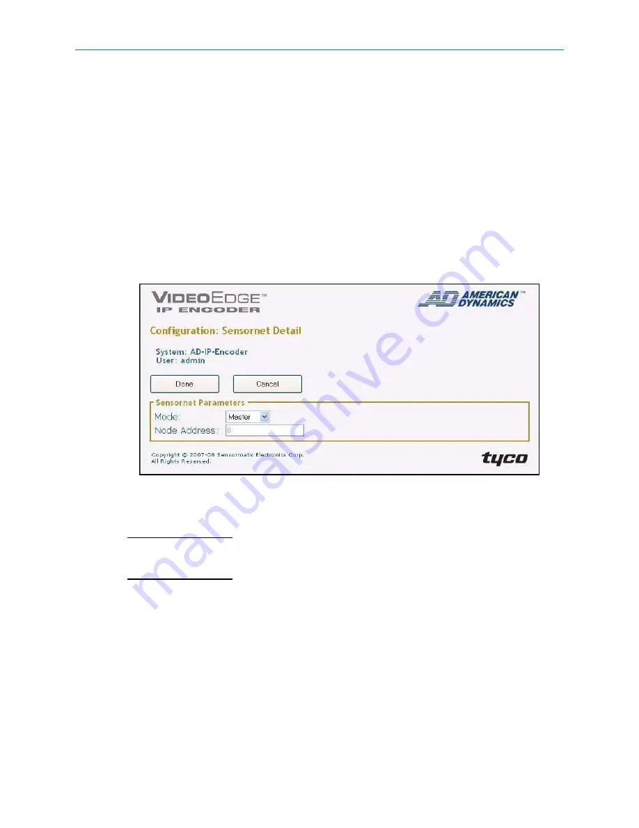
The Sensornet Detail page will be displayed, as shown in Figure 3-12.

Figure 3-12  

Sensornet Detail page

3

Select 

Master

 from the 

Mode

 drop down menu.The default setting is disabled.

Note

There can be only one Master device on the Sensornet network. 

Note

If the IP Encoder is the first or last device on the Sensornet network the Sensornet terminator 
switch, located on the back of the IP Encoder, must be set to ON. 

4

Enter the required 

Node Address

. The default setting is 

0

.

If the Mode is set to Master the Node Address must be set to 0. The Node Address is in the 
format of a whole decimal number. When the Mode is set to Disabled the Node Address is not 
required.

5

Select 

Done

 to return to the IP Encoder Main Configuration page.

6

If all the required changes have been made to the IP Encoder configuration then select 

Save 

Config

 to ensure all changes have been saved. Refer to Procedure 3-19 for more information 

on saving configuration changes.

Summary of Contents for VideoEdge

Page 1: ...Part Number 8200 0806 00 C0 Installation and User Guide VideoEdge 4 Channel IP Encoder Version 1 02 ...

Page 2: ...work of dealers The dealer through whom you originally purchased this product is your point of contact if you need service or support Our dealers are empowered to provide the very best in customer service and support Dealers should contact American Dynamics at 800 507 6268 or 561 912 6259 or on the Web at www americandynamics net Trademarks Intellex is a registered trademark of Sensormatic Electro...

Page 3: ...ese limits are designed to provide reasonable protection against harmful interference when the equipment is operated in a commercial environment This equipment generates uses and can radiate radio frequency energy and if not installed and used in accordance with the instruction manual may cause interference to radio communications Operation of this equipment in a residential area is likely to caus...

Page 4: ...uch an event you must destroy all copies of the Software and all of its component parts e g documentation hardware box software key The Software may contain software from third parties that is licensed under a separate End User License Agreement EULA Read and retain any license documentation that may be included with the Software Compliance with the terms of any third party EULA is required as a c...

Page 5: ...loss of data or other incidental or consequential damages arising out of your use of or inability to use the Software or its documentation This limitation will apply even if Sensormatic or an authorized representative has been advised of the possibility of such damages Further Sensormatic does not warrant that the operation of the Software will be uninterrupted or error free This limited warranty ...

Page 6: ...vi Installation and User Guide ...

Page 7: ... Checking camera feeds using Live Video function 3 6 Controlling dome cameras on the Live Video page 3 7 Pattern and Preset Camera Controls 3 9 Configuring a Dome Camera 3 11 Configuring the IP Encoder 3 12 System Changing the default language selection 3 14 Security adding or editing user accounts 3 15 Configuring the TCP IP settings 3 17 Configuring the Serial Ports 3 18 Configuring Sensornet 3 ...

Page 8: ... Administrator Front Page 3 5 Figure 3 5 Live Video page 3 6 Figure 3 6 Configuration Main page 3 13 Figure 3 7 System Parameters configuration page 3 14 Figure 3 8 IP Encoder Configuration Security Detail 3 15 Figure 3 9 Add Edit user page 3 16 Figure 3 10 TCP IP configuration page 3 17 Figure 3 11 Serial Port Detail page 3 19 Figure 3 12 Sensornet Detail page 3 20 Figure 3 13 Video Input Detail ...

Page 9: ...1 Procedure 3 11 Accessing the IP Encoder Configuration page 3 12 Procedure 3 12 Changing the default language 3 14 Procedure 3 13 Adding a new user or editing an existing user s details 3 15 Procedure 3 14 Configuring the TCP IP settings 3 17 Procedure 3 15 Configuring the serial ports 3 19 Procedure 3 16 Configuring Sensornet 3 20 Procedure 3 17 Configuring the Video Inputs 3 21 Procedure 3 18 C...

Page 10: ...Table of Contents x Installation and User Guide ...

Page 11: ...ions developed using the Intellex API so it is remotely accessible network ready and easy to integrate with other equipment The IP Encoder is an ACC video encoder that converts analog video from our existing cameras and domes into a network compatible IP signal used by Intellex IP and the Intellex Virtual Matrix System Configurations In order to achieve optimal system performance it is highly reco...

Page 12: ...The VideoEdge IP Video Encoder has the following physical connections 4 Composite BNC 75 ohm connectors for connection to analog cameras 4 RJ45 Serial ports for use with PTZ camera control text input 1 Sensornet port for use with a Sensornet network 4 Event Alarm inputs and 6 Event Alarm outputs output alarms not supported at this release 4 Audio input output one for each camera not supported at t...

Page 13: ...sitivity setting on Intellex IP Resolutions Table 1 2 Resolution Note 1 For use with Live Video feature only Video Loss Detection In the event of video loss an alarm is generated The alarm is automatically cleared when the video is restored Bandwidth Throttling The IP Encoder supports bandwidth throttling and is set on a individual camera and client basis The maximum bandwidth is selectable betwee...

Page 14: ...ut The following supported Camera handlers AD Sensornet AD168 MP48 AD1024 AD RS422 AD RS485 Pelco P Pelco D Philips Bosch Auto Dome Pelco Matrix BBV StarCard Cyberscan I Web Configuration IP Encoder s web configuration page allows you to configure settings and view live video Refer to page 3 1 Web Configuration for more information ...

Page 15: ...nstallations where a number of IP Encoders are to be installed on the same site at the same time The advantage of Method A in this case is the IP Encoders will have their network settings and identification configured before their connection to the Intellex IP This allows easier identification of each IP Encoder when using the Intellex IP to set the video parameters for each device Note Method A m...

Page 16: ...tion 3 Web Configuration and configure the following settings on the IP Encoder TCP IP settings Serial ports Sensornet if applicable Video Inputs Event Inputs if applicable Refer to the IP Encoder Quick Start Guide to install the Encoder to the network and connect the Video feeds Serial ports Sensornet Event In Out and power cables Note If Video feeds are available the Live Video function can also...

Page 17: ... the Intellex Setup Guide and follow the procedure for adding an IP Encoder Note For PoE models there are no power supply cables to connect From within the Intellex select Device Setup for the new IP Encoder This will display the IP Encoder Main Page within a browser window Using the Intellex Setup and User Manuals configure any other required advanced features Refer to section 3 Web configuration...

Page 18: ...Installation 2 4 Installation and User Guide ...

Page 19: ...upported web browsers are as follows Microsoft Internet Explorer 6 x Microsoft Internet Explorer 7 x Minimum PC Requirements Processor 2GHz Intel Pentium 4 Memory 512MB Operating System Microsoft Windows 2000 Professional Microsoft Windows XP Professional Note JavaScript must be enabled to allow the correct viewing of the web configuration pages Note Web Configuration sessions timeout after a peri...

Page 20: ...he IP address 192 168 1 80 This is the default address of the IP Encoder Login Page The main Login page will be displayed as shown in Figure 3 1 Figure 3 1 Login page Note If any alarms or warnings are present on the IP Encoder then these will also be displayed on the login page an example is shown in Figure 3 2 Figure 3 2 Login page with warnings ...

Page 21: ...t browser session Procedure 3 12 must be completed to change the IP Encoder default language 3 Enter the appropriate User Login Name and Password then select Login Depending on the access rights of the user the IP Encoder will display either the Administrator or the User front page Both options are described on the following pages Note The default username is Administrator and the default password...

Page 22: ...ser has logged in Figure 3 3 will be displayed Figure 3 3 User Front Page The options available to the User are Live Video Allows the testing of the attached Analog cameras by viewing live video Refresh Provides a method of updating the System Status of the IP Encoder Logout ...

Page 23: ...istrator are Live Video Allows the testing of the attached Analog cameras by viewing live video Configuration Configures the IP Encoder Backup Config Allows the IP Encoder configuration to be saved to a data file Update Firmware Allows the IP Encoder firmware to be updated Restart Restarts the IP Encoder Refresh Provides a method of updating the System Status of the IP Encoder Logout ...

Page 24: ...Intellex IP The Live Video pages are accessible to any authorized user Note To be able to view the Live Video page JavaScript must be installed and enabled on the computer running the browser session Procedure 3 2 Checking camera feeds using the Live Video function 1 Login to the IP Encoder using an appropriate username and password for more details refer to Login to the IP Encoder on page 3 2 2 S...

Page 25: ...tivity Resolution or Direct Draw settings only affect what is being displayed on the Live Video page Changing these settings does not affect the video being sent by the IP Encoder to the Intellex IP 7 Select Front Page to return to the IP Encoder Front Page or Logout to exit the screen Controlling dome cameras on the Live Video page Dome cameras may be controlled using the on screen controls in th...

Page 26: ...Click the control item on the overlay Iris Open Auto Iris and Focus on cameras which support this feature Close Zoom In Out Focus Near Far Pan Tilt Movement Pan Tilt outer rim Pan Tilt control Flips the camera 180 Opens the preset menu Zoom Focus Iris Opens the pattern menu Opens the dome configuration menu Closes the dome control overlay Exit ...

Page 27: ...if it is supported by the camera and implemented in the PTZ protocol Zoom via Mouse Scroll Wheel Procedure 3 5 Zooming a dome via the mouse scroll wheel using the Live Video page 1 Point the camera at a target 2 Scroll the mouse wheel forwards zoom in and backwards zoom out Pattern and Preset Camera Controls A Preset is a pre positioned camera scene that you program for cameras installed with pan ...

Page 28: ...Click and select an index for pattern 4 Click Define Pattern The Pattern Definition Menu appears It resembles the Primary Camera Control menu except for Start and Stop 5 Click Start to begin programming the pattern Use any displayed controls to define the pattern s behavior 6 To end the pattern click Stop The Replace Pattern message appears 7 To keep the new pattern click Yes or select Cancel 8 Cl...

Page 29: ...essage appears click Yes to program the preset The number of available presets is device dependent Configuring a Dome Camera Depending on the protocol being used cameras can access the dome configuration menu see the Intellex Installation and Configuration Information appearing in the menu depends on the dome camera Procedure 3 10 Configuring a dome using the Live Video page 1 Select the camera Cl...

Page 30: ...al Ports Sensornet Network Event Inputs Note Any changes to the configuration are only saved when Save Config is selected Procedure 3 11 Accessing the IP Encoder Configuration page 1 Login to the IP Encoder refer to Procedure 3 1 2 Select Configuration from the Front Page The Configuration main page will be displayed as shown in Figure 3 6 Note To view the bottom of the main Configuration page it ...

Page 31: ...Web Configuration 3 13 Figure 3 6 Configuration Main page ...

Page 32: ...Procedure 3 11 2 Select Edit from within the System section The System page will be displayed as shown in Figure 3 7 Figure 3 7 System Parameters configuration page 3 Select the required language from the drop down menu 4 Select Done to return to the main Configuration page Note The language will only change once the configuration has been saved and a new browser session opened 5 If all the requir...

Page 33: ...ave been added the Create New User button will be disabled until an existing user has been deleted Note It is recommended that a new Administrator account be created or the default Administrator account User Name or Password be changed Procedure 3 13 Adding a new user or editing an existing user s details 1 Ensure that the browser is displaying the Configuration page if not refer to Procedure 3 11...

Page 34: ...ion rights select Enabled from the Administrator drop down menu The default setting is Disabled for new user accounts 7 Select Done to return to the main security detail page as shown in Figure 3 8 8 If all users have been added or updated then select Done to return to the IP Encoder Main Configuration page 9 If all the required changes have been made to the IP Encoder configuration then select Sa...

Page 35: ...ocedure 3 11 2 Select Edit from within the TCP IP section The TCP IP configuration page will be displayed as shown in Figure 3 10 Figure 3 10 TCP IP configuration page 3 The Server Name is the network name given to the IP Encoder on the TCP IP network The default Server Name is the product name e g ADIPE4 followed by the last 6 digits of the MAC address Enter a new Server Name by deleting the curr...

Page 36: ...iguration page allows the configuration of the serial ports for either PTZ control or Text Input the association of the camera to the serial port is configured using the Video Input configuration page refer to page 3 21 The 4 channel IP Encoder has 4 serial ports each port is configured separately using Procedure 3 15 All serial ports can be configured as RS 232 while only port 2 can also be confi...

Page 37: ...ptions are PTZ Control or Text Input The default setting is PTZ Control Note Unless an external converter is to be used PTZ control can only be used with serial port 2 6 Select the required port Baud Rate from the drop down menu The default value is 9600 7 Select the required Data Bits from the drop down menu The options available are 7 or 8 The default value is 8 8 Select the required Stop Bits f...

Page 38: ...ction The Sensornet Detail page will be displayed as shown in Figure 3 12 Figure 3 12 Sensornet Detail page 3 Select Master from the Mode drop down menu The default setting is disabled Note There can be only one Master device on the Sensornet network Note If the IP Encoder is the first or last device on the Sensornet network the Sensornet terminator switch located on the back of the IP Encoder mus...

Page 39: ...13 Figure 3 13 Video Input Detail page 3 Enter the required Name for the Video Input 4 Select the required Video Format from the drop down menu The options are Auto NTSC and PAL The default setting is Auto which will auto detect the incoming video stream format 5 If using 4 CIF the video is automatically deinterlaced to give better quality on motion To disable deinterlacing select Disable from the...

Page 40: ... a door sensor which when the door is opened triggers an event on the IP Encoder which in turn can be monitored by the Intellex IP to start recording on the associated video input at a higher rate The Event Inputs directly relate to the Video Inputs on the IP Encoder e g Event Input 1 relates to Video Input 1 Procedure 3 18 Configuring the Event Inputs 1 Ensure that the browser is displaying the C...

Page 41: ...t Inputs have been configured and all the required changes have been made to the IP Encoder configuration then select Save Config to ensure all changes have been saved Refer to Procedure 3 19 for more information on saving configuration changes ...

Page 42: ...nfiguration Procedure 3 19 Saving the IP Encoder configuration 1 Ensure that the browser is displaying the Main Configuration page If changes to the configuration have been made the message Changes made to configuration have not yet been permanently saved will be displayed as shown in Figure 3 15 Figure 3 15 Main Configuration page Saving Configuration 2 Select Save Config The IP Encoder configura...

Page 43: ...hanges will revert the IP Encoder to the last saved configuration Procedure 3 20 details the steps required to cancel any changes to the configuration Procedure 3 20 Canceling configuration changes 1 Ensure that the browser is displaying the Main Configuration page if not refer to Procedure 3 11 2 Select Cancel Config The Cancel Config Verify page is displayed as shown in Figure 3 17 Figure 3 17 C...

Page 44: ...and User Guide 3 Select Discard Changes to cancel the changes to the configuration and return to the IP Encoder Front page Note Selecting Return To Config will keep the changes to the configuration and display the Main Configuration Page ...

Page 45: ... to Backup the configuration to a data file Procedure 3 21 Backing up the configuration 1 Ensure that the browser is displaying the Front page if not refer to Procedure 3 11 Select Backup Config 2 Select Save from the pop up dialog box Note The Save dialog window may not appear if the browser is configured to stop pop up windows 3 Select the appropriate location and enter a file name for the confi...

Page 46: ... 3 11 2 Select Restore Config The Load Configuration File page is displayed as shown in Figure 3 18 Figure 3 18 Load Configuration File page 3 Enter the name of the backup file including network path to be used or select Browse and use the file browser to locate and select the backup file 4 Select Load File Note If the file selected is not a valid backup file then the Load Configuration File page ...

Page 47: ...d from the default settings then the upgrade procedure should be completed using a laptop or PC directly connected to the IP Encoder Once the factory default settings are restored on the IP Encoder the IP address will be reset to 192 168 1 80 The laptop or PC connected to the IP Encoder must be reconfigured to the same subnet in order to restore the saved configuration settings Caution Loss of con...

Page 48: ...de page 4 Enter the name of the FUP including network path to be used or select Browse and use the file browser to locate and select the FUP 5 Select Update Firmware The Firmware Update Process page is displayed as shown in Figure 3 20 Figure 3 20 Firmware Updating Progress page ...

Page 49: ...pdate Complete page 6 Select RESTART to restart the IP Encoder and complete the update downgrade procedure 7 Once the IP Encoder has restarted complete Procedure 3 22 to restore the configuration from the configuration backup file Note Upgrading the firmware will result in the IP Encoder s IP address being reset to the factory default of 192 168 1 80 with the default login username Administrator a...

Page 50: ...Web Configuration 3 32 Installation and User Guide ...

Page 51: ... to the factory defaults Procedure 4 1 Restoring the IP Encoder factory defaults Caution Loss of configuration Restoring the factory default will result in all saved configuration settings being removed and the IP Encoder will be restored with the factory settings 1 Ensure that power is being applied to the IP Encoder this can be from either a power supply or an ethernet cable using PoE 2 Press an...

Page 52: ...Restoring factory defaults 4 2 Installation and User Guide ...

Page 53: ...nel connectors Front panel connectors LEDs Figure 5 2 Front panel connectors LEDs Note 1 The Video Alarm LED is not used in this release except during a firmware or configuration upgrade process and during the Power On Self Test POST Com 1 Com 2 Com 3 Com 4 RS 232 Ports Terminal block Video 1 Video 2 Video 3 Video 4 Video Ports Ethernet Port Client Power Restore Button Reset Button Video Alarm Not...

Page 54: ... LEDs rapidly flashing together indicates a firmware or configuration update is in progress Note During the power up process all three LEDs may flash on or off however if all three LEDs are flashing together followed by a short delay and the flash sequence repeated this indicates a Power On Self Test POST error The number of rapid flashes indicates the actual error code Ethernet Port LEDs Green LE...

Page 55: ...signments Pin Description Pin Description 1 RS 422 Tx RS 485 Tx 10 Event Out 2 2 RS 422 Tx RS 485 Tx 11 Event In 3 3 RS 422 Rx 12 Event Out 3 4 RS 422 Rx 13 Event In 4 5 Sensornet 14 Event Out 4 6 Sensornet 15 GND 7 Event In 1 16 Event Out 5 8 Event Out 1 17 GND 9 Event In 2 18 Event Out 6 8 7 6 5 4 3 2 1 Pin Description Pin Description 1 Not Used 5 Tx 2 Not Used 6 CTS 3 RTS 7 GND 4 Rx 8 Not Used ...

Page 56: ...t 1 RS 232 230 kbps max Port 2 RS 232 RS 422 RS 485 2 4 wires 230 kbps max Port 3 RS 232 230 kbps max Port 4 RS 232 230 kbps max Port 5 Sensornet 2 wire All ports protected against accidental Ethernet cable insertion Connectors Port 1 RJ45 Port 2 RJ45 RS 232 RS 422 RS 485 terminal block connector Port 3 RJ45 Port 4 RJ45 Port 5 Sensornet connector terminal block All serial port connectors are capab...

Page 57: ...egulations Category Specification Details Safety UL UL60950 1 CSA C22 2 No 60950 1 TUV EN60950 1 CB IEC60950 1 EMC USA FCC Part 15 class A Canada ICES 003 NMB 003 class A Europe EN55022 class A EN50130 4 Australia New Zealand AS NZS CISPR22 RoHS Complies with European directive 2002 95 EC ...

Page 58: ...Technical specifications 5 6 Installation and User Guide ...

Page 59: ...1 Method A Pre configuration 2 2 Method B Post Configuration 2 3 L Language 3 14 LEDs 5 2 License Software i iv License Information i iv License Grant i iv O Overview 1 1 P Pattern definition 3 9 Pattern and Preset Camera Controls 3 9 Preset definition 3 9 Preset Overlay View 3 10 R Resolution 1 3 S Security configuration 3 15 Sensornet configuration 3 20 Serial Ports configuration 3 18 T TCP IP c...

Page 60: ...Index 6 2 Installation and User Guide ...

Reviews: