American Dynamics SpeedDome Ultra VII RAS917LS Configuration Download Page 61

Displaying Direction Indicators 

Direction Indicators

 let you know the approximate pointing direction of the dome in relation to an 

established point called “North”. Directions for setting the North Position are covered in 

Chapter 4

When enabled, the Direction Indicators appear along the top edge of the display. In addition, a tilt 
elevation indicator also appears along the left edge of the display. The value of the tilt elevation 
indicator is relative to the “virtual horizon” of 0° tilt. By default, the display of Direction Indicators is 
disabled.  

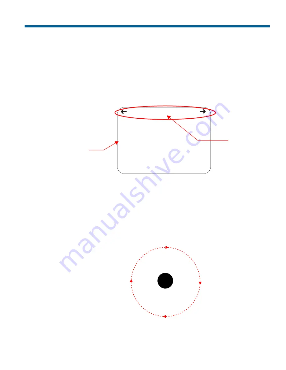
 Figure 5–3 illustrates the locations of the Direction Indicators on the display

Figure 5–3: Screen locations for Direction Indicators 

NE

E

60

12


In this example, the current pointing position is 60° from North. The tilt elevation is 12° above the 
virtual horizon. Panning to the left points the dome towards the Northeast. Panning to the right points 
the dome towards the East. If you tilt below the virtual horizon, the negative values will be displayed 
along the left edge (for example, –25). The elevation values range from +25° to -90°. 

If you pan to a position that corresponds to a well-known navigational heading, the label 
corresponding to the heading appears in the center position. Figure 5–4 illustrates the navigational 
headings and their corresponding degrees from North. 

Figure 5–4: Navigational headings and corresponding degrees from North 


N

45°

135°

180°

90°

270°

315°

225°

NE

E

SE

S

SW

NW

W


In this illustration, the black circle in the center represents the dome, the dotted circle represents the 
pan axis, and the arrowheads represent panning the dome to the right.  

Pointing direction 
around the Pan axis 

(0–359°) 

Tilt elevation/declination

from Horizontal

Dome 

Configuring Text Displayed On-Screen 

5–5


Summary of Contents for SpeedDome Ultra VII RAS917LS

Page 1: ...SpeedDome Ultra VII Day Night Camera Dome RAS917LS RAS917LS 1 RAS917WLS RAS917WLS 1 Configuration Utility Operator s Manual 8200 0184 04 D ...

Page 2: ......

Page 3: ...SpeedDome Ultra VII Day Night Camera Dome Configuration Utility Operator s Manual Version 0710 0147 0107 ...

Page 4: ...ghts reserved under the Copyright Laws of the United States SOFTWARE LICENSE AGREEMENT A Software License Agreement appears in Appendix S of this manual Please read it carefully Using the SpeedDome Ultra VII Camera Dome Configuration Utility software indicates that you accept the terms and conditions of this agreement NOTICE The information in this manual was current when published The manufacture...

Page 5: ...Operates 3 3 Understanding Wide Dynamic Range 3 5 Working with AGC and Open Shutter Settings 3 7 What To Do Next 3 10 CHAPTER 4 CONFIGURING ALARMS AREAS HOME PRIVACY SETTINGS PRESETS AND SCAN LIMITS 4 1 Overview of Alarms Areas Home North Position Preset Privacy and Scan Limit Settings 4 2 Configuring Alarm Actions 4 3 Configuring Normal Input States for Alarms 4 5 Assigning the Dome s Home Positi...

Page 6: ...3 Performance Notes D 4 Programming Presets D 4 Tested Panasonic Equipment D 5 APPENDIX E AD UP THE COAX UTC COMMAND SUMMARY E 1 Command Summary E 2 Supported Controllers E 4 Performance Notes E 4 APPENDIX F VICON COMMAND SUMMARY F 1 Supported SpeedDome Ultra VII Features F 1 Vicon Command Summary F 2 Operating the Dome Configuration Menu F 3 Setting Left and Right Auto Pan Scan Limits F 4 Wiring ...

Page 7: ...ld be familiar with before using the SpeedDome Ultra VII Day Night camera dome It includes a document overview text conventions a list of related documents and how to obtain product help In This Preface What s In This Manual vi Text Conventions vii Related Documents vii Getting Help vii v ...

Page 8: ...unauthorized use of the configuration utility I M P O R T A N T If Portuguese is the selected language the characters ã and õ are not available for display on screen This is due to a limitation of the dome s text overlay chip Chapter 7 Displaying Dome Information explains how to display essential information about your dome if service should be required Appendix A SensorNet and RS 422 Command Summ...

Page 9: ...ion of the product Related Documents Other sources provide supplemental information about your SpeedDome Ultra VII Day Night Camera Dome These sources serve to enhance your understanding of the product and its use The SpeedDome Ultra VII Day Night Camera Dome Configuration Utility Quick Reference Guide 8200 0184 05 provides a brief overview of how to use the configuration utility The SpeedDome Ult...

Page 10: ...N O T E S viii SpeedDome Ultra VII Day Night Operator s Manual ...

Page 11: ...m open shutter settings privacy zones direction indicators and freeze frame The Dome Configuration Utility is used to customize the camera dome s settings This chapter introduces you to the Dome Configuration Utility It explains how to start the utility navigate through the menus and change settings It also explains where to find specific information about customizing dome settings In This Chapter...

Page 12: ...rNet or RS 422 environment press and hold Iris Open press and hold a Focus button near or far then press Zoom Out If the dome is installed in a Manchester environment place the controller in programming mode turn the keyswitch to Prog or disable the lock enter 66 and press Set Preset Set Shot Note Other protocols and controllers may be supported The Appendixes located at the end of this manual pro...

Page 13: ...ing move the cursor to the right of the current character in the name Zoom In During naming move the cursor to the left of the current character in the name Zoom Out Save changes and exit the utility from any screen Iris Close then Focus Entering the Dome s Password A dome password can be used to prevent unauthorized users from starting the configuration utility If password protection is enabled t...

Page 14: ...ssword contact your Sales Representative for assistance For information about programming and enabling password protection see Chapter 6 Restoring Factory Settings Some screens provide a choice to restore factory settings This choice applies only to those settings currently displayed on the screen To reset all configuration settings choose Reset to Factory Settings from the Dome Configuration Menu...

Page 15: ...ess Focus to accept the displayed option I M P O R T A N T The following settings do not restore when selecting Quit Without Saving from the Dome Configuration Menu Area Boundaries and AGC Shutter Limit Accessing the Quick Set Menu SpeedDome Ultra VII Day Night provides a Quick Set Menu for commonly used features and functions when used with compatible controllers This allows you to change or acti...

Page 16: ...ing when the light level is constant or changes in lighting conditions are gradual 15 Quick Set Initiates a smooth scan between the left and right scan limits starting at the left scan limit If no scan limits have been set initiates a smooth 360 clockwise rotation around the dome axis using the current tilt zoom and focus settings 16 Quick Set Initiates a scan between the left and right scan limit...

Page 17: ...omatic or manual Gain settings and set maximum gain values Chapter 4 Configuring Alarms Areas Home Privacy Settings and Presets Set alarm actions to initiate a preset pattern or no action when alarm conditions are detected Configure normal input states for alarms to be open or closed Send input states to host controller Set a home position for dome Establish a North position for use with the direc...

Page 18: ...ls Appendix D Panasonic Up the Coax Command Summary Summarizes the controller commands available for Panasonic UTC protocol Performance limitations for UTC protocol Appendix E AD Up the Coax Command Summary Summarizes the controller commands available for AD UTC protocol Appendix F Vicon Protocol Command Summary Summarizes the controller commands available for Vicon protocol Appendix R Dome Config...

Page 19: ... the Zoom Stop settings set the Line Lock option and configure the Freeze Frame setting In This Chapter Overview of Pan Tilt Zoom Synchronization Options Screen 2 2 Setting the Automatic Flip Feature 2 2 Adjusting the Zoom Stop Settings 2 3 Configuring the Line Lock Setting 2 4 Configuring the Freeze Frame Setting 2 5 Configuring Auto Iris Auto Focus Resume Settings 2 6 What To Do Next 2 7 ...

Page 20: ...ck someone who walks directly under the dome and continues on the other side You start the flip by moving the tilt control to its lower limit and holding for a brief period When the flip engages the dome automatically rotates 180 You may then continue to track the person as long as the tilt control stays in its lower limit Once the tilt control is released the dome resumes normal operation The dom...

Page 21: ...the first zoom stop setting 35X and the zoom button is released for one second or longer To achieve higher zoom levels change the maximum zoom setting 2X is the margin of error for the zoom stop settings Changing the Zoom Stop Settings 1 Select Pan Tilt Zoom Sync Opts from the Dome Configuration Menu 2 To change the first zoom stop continue with step 3 To change the maximum zoom setting continue w...

Page 22: ...e Dome Configuration Menu 2 Move the highlight bar to Line Lock Change the setting Select On to enable the line lock This phase locks the video with the AC power line to prevent video rolling Select Off to disable the line lock This stops the phase lock but may improve the appearance of text displayed on color monitors The default setting is On I M P O R T A N T Changing the Line Lock setting is n...

Page 23: ...oor plan for the lobby Figure 2 1 Lobby Floor Plan If Freeze Frame is enabled the current scene is displayed on screen until all dome movement and lens adjustments are complete For example the Reception Desk scene will be frozen on screen until the dome completes the movement and lens adjustments necessary to display the selected preset When the adjustments are finished the Entry scene is automati...

Page 24: ...iption ON Both return to auto iris and return to auto focus settings are enabled Moving the dome resumes auto mode for both iris and focus changes OFF Both return to auto iris and return to auto focus settings are disabled Moving the dome does not resume auto mode for iris and focus changes IRIS Only return to auto iris is enabled Return to auto focus is disabled Moving the dome resumes auto iris ...

Page 25: ...TINGS QUIT WITHOUT SAVING EXIT AND SAVE CHANGES From this screen you can Chapter 2 Chapter 3 Chapter 4 Chapter 5 Chapter 7 Chapter 6 Chapter 1 Select an option to make additional changes Restore all settings to the factory defaults Exit the utility without saving changes Save the changes and exit the utility Move the highlight bar to an item and select it Refer to the related chapter for additiona...

Page 26: ...N O T E S 2 8 SpeedDome Ultra VII Day Night Operator s Manual ...

Page 27: ...ed from the Dome Configuration Menu the following screen appears CAMERA FUNCTIONS Auto White Bal OFF ON W Bal Adj Red 0 511 Blue 0 511 IR Mode OFF ON Auto High Auto Mid Auto Low WDR OFF ON AGC Shutter Max Gain Limit Open Shutter NTSC 0 28 dB 1 2 1 60 s RESET TO FACTORY SETTINGS EXIT Open Shutter PAL 0 28 dB 2 3 1 50 s From this screen you can adjust the white balance settings set the IR mode for t...

Page 28: ...chart illustrates the red and blue settings relationship to white balance As the value for the red setting increases the image appears more red As the value decreases the image appears less red As the value for the blue setting increases the image appears more blue As the value decreases the image appears less blue As the values for both the red and blue settings are increased the image appears mo...

Page 29: ...of 5 There is no default value for the blue setting 7 Select Exit The Dome Configuration Menu appears Continue with What To Do Next on page 3 10 Understanding How IR Black White Mode Operates SpeedDome Ultra VII Day Night provides a black and white B W mode to improve camera performance when the light level falls below certain thresholds This allows clear images to be obtained under low light cond...

Page 30: ...tinue with What To Do Next on page 3 10 Manually Activating or Deactivating the IR Mode The IR mode may be activated or deactivated using a combination of keyboard commands This allows you to change between color and B W modes as needed To change the mode using SensorNet or RS 422 protocols press and hold Iris Open press and hold Focus Far then press Focus Near To change the mode using Manchester ...

Page 31: ...om and distortion occurs Without WDR you could adjust the iris of the camera to compensate for the lighting change however you cannot clearly see both activities inside and outside of the loading dock area simultaneously For example if you close the iris the outside scene will improve but the interior scene will become too dark to view clearly In Figure 3 2 the car near the loading dock door can b...

Page 32: ...ormal characteristic of WDR operation Changing the Wide Dynamic Range Setting 1 Select Camera Functions from the Dome Configuration Menu 2 Move the highlight to the WDR field Change the setting Select OFF to disable wide dynamic range Use this setting when the light level is constant or changes in lighting conditions are gradual Select ON to enable wide dynamic range Use this setting when both bri...

Page 33: ...uations For more information continue with Understanding How Advanced Shutter Settings Improve Low Light Performance Understanding How Advanced Shutter Settings Improve Low Light Performance The camera dome supports the ability to view color images from extremely low light situations This feature is called Open Shutter and is only in effect during low light situations where an image would not be o...

Page 34: ...ed Light Red Light Red Green Light Green Light 125 msec 250 msec 125 msec Adjusting the Shutter Limit sets the update time used to maintain the image quality If you want to videotape an incident in low light conditions you may find that tape quality is not acceptable To ensure that the videotape quality is acceptable for possible prosecution purposes you may want to test the Shutter Limit settings...

Page 35: ...ontinue with step 7 Select Open Shutter to enable field integration This allows you to adjust the maximum AGC gain and shutter limit settings Continue with step 4 The default setting is Open Shutter 4 Move the highlight to Max Gain field Change the setting The following settings are available For NTSC cameras the setting values range from 0 to 28dB For PAL cameras the setting values range from 0 t...

Page 36: ...RY SETTINGS QUIT WITHOUT SAVING EXIT AND SAVE CHANGES From this screen you can Chapter 1 Chapter 7 Chapter 5 Chapter 3 Chapter 6 Chapter 4 Chapter 2 Select an option to make additional changes Restore settings to the factory defaults Exit the utility without saving changes Save the changes and exit the utility Move the highlight bar to an item and select it Refer to the related chapter for additio...

Page 37: ...t a default position for the dome and assign a dome position that corresponds with North It also explains how to program Areas Privacy Zones Presets and Scan Limits In This Chapter Overview of Alarms Areas Home North Position Preset Privacy and Scan Limit Settings 4 2 Configuring Alarm Actions 4 3 Configuring Normal Input States for Alarms 4 5 Assigning the Dome s Home Position 4 6 Setting the Nor...

Page 38: ... ZONES PRESETS SCAN LIMITS EXIT From this menu you can choose to configure alarm actions configure normal states for alarm inputs assign the home position establish the north position for the dome set area boundaries set privacy zones and program presets To make changes select a menu item to display the associated settings To change the settings move the highlight bar to appropriate field and make...

Page 39: ...ormal When Set Alarm Actions is selected from Alarms Areas Home Presets PZ screen the following screen appears SET ALARM ACTIONS INTERNAL ALARMS INPUT NO ACTION 1 NO ACTION 2 PRESET 1 96 3 PATTERN 1 3 4 NO ACTION SEND INPUTS TO HOST YES NO EXIT Use this screen to assign a preset or pattern to occur whenever the alarm s input state changes from normal to abnormal You may also choose to have no acti...

Page 40: ...on 4 Move the highlight bar to the Action Number field and select the action number For preset select the number from 1 through 96 Continue with step 5 Note The protocol or controller used may support fewer presets Refer to the appropriate Appendix for additional information For pattern select the number from 1 through 3 for the pattern you want to assign Continue with step 5 If the selected patte...

Page 41: ...sed and an alarm is issued To configure the normal state for the alarm select Set Alarm States from the Alarm Areas Home Presets PZ screen The following screen appears SET ALARM STATES INPUT NO NORMAL STATE 1 OPEN CLOSED 2 OPEN CLOSED 3 OPEN CLOSED 4 OPEN CLOSED EXIT Use this screen to assign open or closed as the normal state for the dome alarm inputs When an input state changes from normal to ab...

Page 42: ...arms Areas Home Presets PZ screen appears select Exit The Dome Configuration Menu appears Continue with What To Do Next on page 4 20 Assigning the Dome s Home Position The home position is a preset or pattern that automatically runs after a designated period of dome inactivity Use this option if you want to keep a specific area to be under surveillance whenever the dome is not moving To assign the...

Page 43: ...iate Appendix for additional information For pattern select the number from 1 through 3 for the pattern you want to assign Continue with step 5 If the selected pattern is not programmed the dome runs the Apple Peel pattern 5 Move the highlight bar to Return Time Mins Set the amount of time that the dome must remain inactive before returning to the home position The setting ranges from 1 to 60 minu...

Page 44: ...o called azimuth For more information about Direction Indicators see Chapter 5 Programming the North Position 1 Select Alarms Areas Home Presets PZ from the Dome Configuration Menu 2 Select Set North Position The Set North Position screen appears SET NORTH POSITION PAN to new north position ZOOM to mark north position FOCUS quits w o changing 3 Point the dome to the new North position When satisfi...

Page 45: ...st area cannot go past the starting point of the first area In this example the area that includes the vending machines cannot extend past the starting point of the area that includes the emergency exit If your controller supports areas these are separate from the areas you can program with the dome You should not use both the controller and the configuration utility to define areas The zoom level...

Page 46: ...aries by selecting Quit Without Saving from the Dome Configuration Menu once you begin making changes to the boundaries Setting Area Boundaries 1 Select Alarms Areas Home Presets PZ from the Dome Configuration Menu 2 Move the highlight bar to Area Boundaries then select The Area Boundaries screen appears 3 Adjust the camera to the starting point of the first area and press Zoom to mark the boundar...

Page 47: ...o the dome pan tilt position In addition the apparent size of the Privacy Zone adjusts automatically as the zoom level is adjusted Up to eight Privacy Zones may be established for a dome Privacy Zones are useful for high security areas For example you might establish a Privacy Zone around a safe s combination However you could view people approaching or opening the safe When Privacy Zones are acti...

Page 48: ...mage to mask The fourth point on the Privacy Zone is automatically generated by mirroring the longest axis between the three selected points Figure 4 2 illustrates how Privacy Zones are programmed Figure 4 2 Privacy Zone programming example The dome s firmware prevents you from establishing a zone that is too small or too large greater than 90 degrees pan or tilt from the starting point Figure 4 3...

Page 49: ...Number of Zones Defined Pressing Focus Far returns to the Program Privacy Zones screen To program a new zone you must delete at least one of the eight existing Privacy Zones See Removing or Hiding Privacy Zones on page 4 14 I M P O R T A N T Areas of the Privacy Zone may be exposed during rapid pan tilt movements of the dome To compensate for this limitation you may want to program the Privacy Zon...

Page 50: ... Privacy Zones are illustrated Zones 1 and 2 are overlapping Zone 1 and 3 are in close proximity In this situation the arrows blink because the target area is the same distance from all three zones To ensure that the correct Privacy Zone is deleted place the arrows clearly in the zone you want to delete Figure 4 5 illustrates a valid selection Figure 4 5 Deleting Privacy Zone Valid Selection Navig...

Page 51: ...prompt appears on screen You are about to delete All Privacy Zones Cancel Continue 5 To delete all Privacy Zones select Continue If you do not want to delete all Privacy Zones select Cancel The Program Privacy Zones screen displays 6 Select Exit to return to Alarms Areas Home Presets PZ screen 7 When the Alarms Areas Home Presets PZ screen appears select Exit The Dome Configuration Menu appears Co...

Page 52: ...ine on those systems as the home position or an alarm action You must use the presets programmed using this utility AD168 matrices with an AD168CCM control code module support Manchester RS 422 and SensorNet networks and provide 64 virtual views All other AD matrices support Manchester and 64 dome presets or RS 422 networks and provide 16 virtual views when the AD2083 02A code unit is used Setting...

Page 53: ...upted by a camera command preset pattern or alarm Understanding Scan Limits Scan Limits are two points around the pan axis that define a surveillance area When a scan is activated the dome pans between the two surveillance points the left and right scan limits This helps to ensure that only useful video is being monitored during the scan For example a dome is mounted off the edge of a building to ...

Page 54: ...scan limit When the right scan limit is reached the scan reverses Figure 4 6 illustrates the smooth scan A stepped scan pans slowly pausing briefly every 10 between the left and right scan limits Once the right scan limit is reached the scan reverses Figure 4 7 illustrates the stepped scan Each arrowhead represents a 10 step in the scan Figure 4 7 Stepped Scan Left Scan Limit Parking Lot Building ...

Page 55: ...ion Figure 4 8 Random Scan 2 First pause 4 Third pause Change direction 1 Random scan starts Left Scan Limit Parking Lot Building 3 Second pause Change direction Dome Right Scan Limit 5 Right scan limit reached Change direction Programming Scan Limits Note Scan Limits can only be used with controllers that support the Quick Set menu The Quick Set menu is not available for domes used with the Manch...

Page 56: ... Dome Configuration Menu appears DOME CONFIGURATION MENU PAN TILT ZOOM SYNC OPTS CAMERA FUNCTIONS ALARMS AREAS PRESETS PZ ON SCREEN TEXT DISPLAY LANGUAGE PASSWORD DOME INFORMATION RESET TO FACTORY SETTINGS QUIT WITHOUT SAVING EXIT AND SAVE CHANGES From this screen you can Chapter 2 Chapter 3 Chapter 4 Chapter 5 Chapter 6 Chapter 7 Chapter 1 Select an option to make additional changes Restore all s...

Page 57: ... 5 7 Changing the Settings for Text Displayed On Screen 5 9 What To Do Next 5 11 Overview of On Screen Text Display Settings When On Screen Text Display is selected from the Dome Configuration Menu the following screen appears ON SCREEN TEXT DISPLAY STATUS DISPLAY ON OFF DISABLE ALL NAMES YES NO DIAGNOSTIC DISPLAY ON OFF DIRECTION INDICATOR ON OFF NAME CONFIGURATION MENU TEXT ATTRIBUTE OPTIONS EXI...

Page 58: ...FF AUTO FOCUS ON Note Displaying status information is separate from displaying name information If the Disable All Names setting is set to Yes the status information still appears if Status Display is set to On Changing the Display of Status Information 1 Select On Screen Text Display from the Dome Configuration Menu The highlight bar appears on Status Display 2 Change the setting Select On to di...

Page 59: ... AREA NAME You may choose to disable displaying all name information or you may choose to display selected or all name information Changing the Display of All Name Information 1 Select On Screen Text Display from the Dome Configuration Menu 2 Move the highlight to Disable All Names 3 Change the setting Select Yes to disable the appearance of all name information Select No to enable the appearance ...

Page 60: ...nostic tests may cause a momentary loss of communication on the network when the dome diagnostics are executed Changing the Display of Diagnostic Information 1 Select On Screen Text Display from the Dome Configuration Menu 2 Move the highlight to Diagnostic Display 3 Change the setting If you want diagnostic tests to run when the dome resets select On If you do not want diagnostic tests to run whe...

Page 61: ...ion is 12 above the virtual horizon Panning to the left points the dome towards the Northeast Panning to the right points the dome towards the East If you tilt below the virtual horizon the negative values will be displayed along the left edge for example 25 The elevation values range from 25 to 90 If you pan to a position that corresponds to a well known navigational heading the label correspondi...

Page 62: ...xit The Dome Configuration Menu appears Continue with What To Do Next on page 5 11 Configuring the Display of Name Information Use the Name Configuration Menu to select which name information appears on screen To display this screen select Name Configuration Menu from the On Screen Text Display screen The following screen appears NAME CONFIGURATION MENU CAMERA NAME ON OFF AREA NAME ON OFF PRESET N...

Page 63: ... following prompt appears on the screen RESET PROGRAMMABLE NAMES NO To reset all names to the default value select Yes The Name Configuration Menu displays Programmable Names Have Been Reset appears at the bottom of the screen To cancel resetting of names select No The Name Configuration Menu displays The default selection is No 8 Do one of the following To change programmable name information con...

Page 64: ...RN AREA ALARM 1 3 Pattern 1 3 1 16 Area 1 16 1 4 Alarm 1 4 Note Gray text refers to other options that may appear on screen 5 Press Zoom to change the number When the item whose name you want to change appears press Focus Far Note If Presets Patterns or Areas have been programmed the dome automatically points to the starting position of the associated selection each time the number is advanced 6 T...

Page 65: ...ype of name selected in step 3 repeat steps 4 through 10 To return to the Name Configuration Menu select Exit and continue with step 12 12 Do one of the following To make additional name changes repeat steps 3 through 11 To return to On Screen Text Display select Exit Continue with step 13 13 Select Exit The Dome Configuration Menu appears Continue with What To Do Next on page 5 11 Changing the Se...

Page 66: ...ions screen appears The highlight bar appears on Character Outline 3 Change the setting Select On to display text with an outline around each character Select Off to display without an outline around each character The default setting is On 4 Do one of the following If you want to change the text appearance for dome names and status information move the highlight bar to Translucent Names Continue ...

Page 67: ...RMATION RESET TO FACTORY SETTINGS QUIT WITHOUT SAVING EXIT AND SAVE CHANGES From this screen you can Chapter 2 Chapter 3 Chapter 4 Chapter 5 Chapter 7 Chapter 6 Chapter 1 Select an option to make additional changes Restore all settings to the factory defaults Exit the utility without saving changes Save the changes made and exit the utility Move the highlight bar to an item and select it Refer to ...

Page 68: ...N O T E S 5 12 SpeedDome Ultra VII Day Night Operator s Manual ...

Page 69: ...uage and Password Settings When Language Password is selected from the Dome Configuration Menu the following screen appears LANGUAGE PASSWORD LANGUAGE SELECTION SET PASSWORD PASSWORD PROTECTION OFF EXIT ON From this screen you can choose the language for the menus status information and prompts from the dome You can also set and enable the use of the dome password To make changes select a menu ite...

Page 70: ...uage Password from the Dome Configuration Menu 2 Select Language Selection The Language Selection screen appears LANGUAGE SELECTION ENGLISH SPANISH FRENCH GERMAN ITALIAN PORTUGUESE EXIT Move the highlight bar to the preferred language setting The default setting is English 3 Select the highlighted language The following screen appears DOME MUST RESET TO CHANGE LANGUAGE SELECT CONTINUE TO RESET CON...

Page 71: ...the current language setting Setting or Changing the Dome Password 1 Select Language Password from the Dome Configuration Menu 2 Select Set Password The Set Password screen appears SET PASSWORD PASSWORD A B C D E F G H I J K L M N O P Q R S T U V W X Y Z a b c d e f g h i j k l m n o p q r s t u v w x y z 0 1 2 3 4 5 6 7 8 9 CONTINUE CANCEL 3 Move the blinking highlight around the available charac...

Page 72: ...he dome What T Next o Do When you select Exit from the Language Password screen the Dome Configuration Menu appears DOME CONFIGURATION MENU PAN TILT ZOOM SYNC OPTS CAMERA FUNCTIONS ON SCREEN TEXT DISPLAY LANGUAGE PASSWORD DOME INFORMATION RESET TO FACTORY SETTINGS QUIT WITHOUT SAVING EXIT AND SAVE CHANGES From ou can ake additional changes Restore all settings to the factory defaults Exit the util...

Page 73: ... you view this screen you can determine the dome type mnemonic software version serial number and manufacture date DOME INFORMATION NAME SpeedDome Ultra VII Mnemonic SDU 7 Software Ver 0710 0147 0100 Device Type 24770105 SN 01234567890123456789 Manufacture Date 11012002 Dome Statistics EXIT The information that appears on the Dome Information screen cannot be changed or altered This feature is pro...

Page 74: ...ts either runtime in seconds or number of occurrences displayed in hexadecimal values The following table describes the abbreviations used Abbreviation Description R Time moving right in seconds L Time moving left in seconds M Total move time in seconds T Total target count O Operating time in seconds P Power failure reset count W Watchdog reset count The watchdog tracks software problems that cau...

Page 75: ... TO FACTORY SETTINGS QUIT WITHOUT SAVING EXIT AND SAVE CHANGES From this screen you can Chapter 2 Chapter 3 Chapter 4 Chapter 5 Chapter 6 Chapter 7 Chapter 1 Select an option to make additional changes Restore all settings to the factory defaults Exit the utility without saving changes Save the changes and exit the utility Move the highlight bar to an item and select it Refer to the related chapte...

Page 76: ...N O T E S SpeedDome Ultra VII Day Night Operator s Manual 7 4 ...

Page 77: ...ppendix summarizes the SensorNet and RS 422 controller commands used with the Configuration Utility It also provides a list of compatible controllers In This Appendix Command Summary A 2 Supported Controllers and Matrix Switching Systems A 3 Performance Notes A 6 ...

Page 78: ...t Save changes and exit the utility from any screen Iris Close then Focus Manually activate or deactivate IR mode Press and hold Iris Open press and hold Focus Far then press Focus Near These commands not supported with MPLT with ADCC0200 or ADCC0300 controller Refer to the appropriate operator s manual for instructions Setting Names Working with Passwords When setting names or entering password i...

Page 79: ...s 1 Apple Peel only Programmable patterns are not available VM16 ADTT16 White Touch Tracker Supported Protocols SensorNet RS 422 1 Maximum Presets 96 SensorNet 4 RS 422 Maximum Patterns 2 3 Quick Set Menu Not supported Address Range 1 16 Notes 1 Requires RCSN422 code converter 2 Patterns are limited by time and the number of available dome commands Total time for each pattern cannot exceed 6 minut...

Page 80: ...e AD2083 02 series code converter 2 Preset information is stored at the converter not the dome 3 Requires AD2083 02 with firmware version 0701 11YB 156A or newer Preset information is stored in the dome not the converter 4 Patterns are limited by time and the number of available dome commands Total time for each pattern cannot exceed 6 minutes 50 seconds Total dome commands used in all patterns ca...

Page 81: ...mbers A dome address within each group of 64 or 99 cameras is reserved as a global broadcast address MegaPower LT Supported Protocol SensorNet Maximum Presets 96 Maximum Patterns 1 3 Quick Set Menu Yes 2 Address Range 1 32 Notes 1 Patterns are limited by time and the number of available dome commands Total time for each pattern cannot exceed 6 minutes 50 seconds Total dome commands used in all pat...

Page 82: ... domes to be specified at the controller VM16 Plus ADTT16 ADTT16E VM32 AD32 AD32E VM96 Touch Tracker 16 Elite AD matrices with AD2083 02A code units AD168 MP168 with CCM or AD2083 02A Do not use both the dome configuration utility and the controller to assign the alarm actions for the same input Use only the dome configuration utility or the controller to the assign the alarm actions A 6 SpeedDome...

Page 83: ...the Manchester controller commands used with the Configuration Utility It also provides a list of additional Manchester commands that can be used with the dome and compatible controllers In This Appendix Command Summary B 2 Supported Controllers B 4 Performance Notes B 4 ...

Page 84: ...Zoom setting Zoom In Display the previous choice for the setting For example Maximum Zoom setting Zoom Out Save changes and exit the utility from any screen Iris Close then Focus Setting Names Working with Passwords When setting names or entering password information the screen displays the available characters in the selected languages In these situations the following commands are used If you wa...

Page 85: ...adjustment 67 Set Preset Cancel Pattern Programming 68 Set Preset Save Pattern Programming 69 Set Preset Program Pattern 1 70 Set Preset Program Pattern 2 71 Set Preset Program Pattern 3 72 Set Preset Call Commands This table describes the functions that can be performed when you enter the number listed then press the Call Preset button If you want to Use Resume Auto Focus Auto Iris 66 Call Preset...

Page 86: ...hould be made when using the SpeedDome Ultra VII Day Night camera dome in a Manchester environment Using Auxiliaries The dome provides four connections for auxiliaries When used on a Manchester network Auxiliaries 1 through 3 are supported Auxiliary 4 is not supported Alarm Inputs When operating on a Manchester network the dome can be programmed to respond to any of the four available alarm inputs...

Page 87: ...oaxitron and P protocols In addition it provides the controller commands used with the Configuration Utility It also supplies information about tested Pelco equipment and supported Pelco features In This Appendix Supported SpeedDome Ultra VII Features C 2 Pelco Command Summary C 3 Performance Notes C 4 Tested Pelco Equipment C 4 Supported Pelco Features C 4 ...

Page 88: ... Mode Wide Dynamic Range WDR Proportional Flip Freeze Frame Direction Indicator display Multi language Dome Configuration Utility available in English French German Italian Portuguese and Spanish with Password Protection Unsupported SpeedDome Ultra VII Features The following SpeedDome Ultra VII features are not supported with the Pelco Coaxitron and P protocols Save and exit from configuration men...

Page 89: ... Setting Names Working with Passwords When setting names or entering password information the screen displays the available characters in the selected languages In these situations the following commands are used If you want to Use Move the highlight left or right in the character field Pan Move the highlight up or down in the character field Tilt Select the highlighted character in the character ...

Page 90: ...be set to 0 the x10 and x1 switches may be set to any number For 9600 baud the x100 switch must be set to 7 the x10 and x1 switches may set to any number Tested Pelco Equipment The following Pelco equipment has been tested with SpeedDome Ultra VII Pelco 9760CTX Pelco MPT 9500 Supported Pelco Features SpeedDome Ultra VII supports Left and Right Scan Limits Auto Scan Frame Scan and Random Scan when ...

Page 91: ...osition the dome s pointing direction to the Left Scan Limit 3 Enter Set Preset 92 to save the setting 4 Position the dome s pointing direction to Right Scan Limit 5 Enter Set Preset 93 to save the setting Activating Auto Scan Auto Scan allows the dome to continuously pan between the left and right scan limit settings When reaching the right scan limit the direction is automatically reversed If no...

Page 92: ... a pan tilt or lens command also stops the scan Activating Random Scan Random Scan pans between the left and right scan limits for random periods between 1 and 9 seconds then pauses for periods between 1 and 9 seconds If the scan limits are not programmed the Random Scan pans to the right for random periods between 1 and 9 seconds then pauses for periods between 1 and 9 seconds To activate the Ran...

Page 93: ...he Panasonic UTC protocol In addition it provides the controller commands used with the Configuration Utility It also provides information about tested Panasonic equipment In This Appendix Supported SpeedDome Ultra VII Day Night Features D 2 Panasonic UTC Command Summary D 3 Performance Notes D 4 Programming Presets D 4 Tested Panasonic Equipment D 5 ...

Page 94: ...ortional Flip Direction Indicator display Dome Configuration Utility available in English French German Italian Portuguese and Spanish with Password Protection Unsupported SpeedDome Ultra VII Features The following SpeedDome Ultra VII features are not supported with the Panasonic UTC protocol Save and exit from configuration menus using Iris Close and Focus keys Patterns V Phase adjustment PAL vid...

Page 95: ...hoice for the setting For example Maximum Zoom setting Left Adjust dome position during menu programming ALT Setting Names Working with Passwords When setting names or entering password information the screen displays the available characters in the selected languages In these situations the following commands are used If you want to Use Move the highlight left or right in the character field ALT ...

Page 96: ...ust use the Dome Configuration Menu to program Presets Up to 64 Presets may be programmed Note This procedure has been verified using the following equipment WJ SX550 Multiplexer WV CU550A Controller 1 Select the monitor and camera number assigned to the Speed Dome Ultra VII camera dome 2 Use the arrow keys on the controller to scroll to the Camera Setup Menu D4 3 Press F1 On key to display the Do...

Page 97: ...pan tilt position PRESETS PRESET X Position camera with PAN TILT ZOOM and IRIS FOCUS FAR to save and exit EXIT IMPORTANT If using the WV CU550A Controller with the WJ SX550 Multiplexer you must press F3 A Res to adjust the zoom focus or iris settings This places the controller in normal navigating mode Make the necessary adjustments When finished press F1 On to resume menu mode 8 Press Set to save...

Page 98: ...N O T E S D 6 SpeedDome Ultra VII Day Night Operator s Manual ...

Page 99: ...marizes the AD UTC controller commands used with the Configuration Utility It also provides a list of additional AD UTC commands that can be used with the dome and compatible controllers In This Appendix Command Summary E 2 Supported Controllers E 4 Performance Notes E 4 ...

Page 100: ...or example Maximum Zoom setting Zoom In Display the previous choice for the setting For example Maximum Zoom setting Zoom Out Save changes and exit the utility from any screen F Function and then Shift Clear Setting Names Working with Passwords When setting names or entering password information the screen displays the available characters in the selected languages In these situations the followin...

Page 101: ...t Preset number Preset number then Preset Start selected Pattern programming F pattern number Function pattern number 1 3 then Shift Preset Save Pattern programming Pattern number F Pattern number 1 3 then Function Run selected Pattern continuously Pattern number then and Pattern number Shift and Preset Resume Auto Focus mode F or F Function Focus Far or Function Focus Near Resume Auto Iris mode F...

Page 102: ...lizes or resets the address and protocol information UTC_T appear on screen Accessing the Quick Set Menu The Quick Set Menu provides easy access to certain SpeedDome Ultra VII Day Night functions from the keyboard Two pages of settings are available To access the Quick Set menu select the dome and press Quick Set button Figure E 1 Quick Set Menu 0 TOGGLE QUICK SET MENU 1 DOME CONFIG MENU 2 AUTO IR...

Page 103: ...ighting conditions are gradual 15 Smooth Scan Initiates a smooth scan between the left and right scan limits starting at the left scan limit If no scan limits have been set initiates a smooth 360 clockwise rotation around the dome axis using the current tilt zoom and focus settings 16 Stepped Scan Initiates a scan between the left and right scan limits pausing briefly every 10 at 1x zoom starting ...

Page 104: ...E 6 SpeedDome Ultra VII Day Night Operator s Manual ...

Page 105: ...and Right Auto Pan Scan Limits F 4 Wiring Configurations F 5 Tested Vicon Equipment F 6 Supported SpeedDome Ultra VII Features The following SpeedDome Ultra VII features are supported with the Vicon protocol 10x digital zoom up to 230X total zoom for SpeedDome Ultra VII Day Night dome 79 Total Presets 1 79 3 Patterns 16 Areas 4 Alarm Inputs and Outputs 8 Privacy Zones Programmable Names camera pre...

Page 106: ... to PGM Enter 86 Enter Review Pattern Run Pgm switch to PGM Enter 87 Enter Accept Pattern Run Pgm switch to PGM Enter 88 Enter Run Pattern 1 3 Run Pgm switch to RUN Enter 80 82 Enter Repeat Pattern 1 3 Run Pgm switch to RUN Enter 83 85 Enter Set Pattern to Peel Enter 89 Enter Vphase Dome Note The A I LED blinks indicating that you are in the vphase mode Enter key sequence again to turn vphase adju...

Page 107: ...uration utility when the dome is installed in a Vicon environment If you want to Use Start the configuration utility Run Pgm switch to PGM Enter 94 Enter Move the highlight bar on the active menu Tilt Up Down Select the highlighted item on the active menu A P or AUX5 Increase the value of the selected setting For example Red or Blue white balance values Pan Right or Zoom In Decrease the value of t...

Page 108: ...g Left and Right Auto Pan Scan Limits I M P O R T A N T You must program the Left Scan Limit setting before programming the Right Scan Limit setting This procedure erases any previously programmed Right Scan Limit setting Programming the Scan Limits 1 Select the camera number assigned to the SpeedDome Ultra VII dome 2 Use the pan tilt joystick to position the dome s pointing direction to the Left ...

Page 109: ...ngs are programmed the dome pans to the right continuously Note Auto Pan will be cancelled if the operator issues a Pan Flip Preset or Pattern command Wiring Configurations In Vicon systems where the domes support loop through daisy chain the SpeedDome Ultra VII domes off the last Vicon dome in the communications chain Figure F 1 SpeedDome Ultra VII dome loop through wiring from Vicon dome To cont...

Page 110: ...ltra VII dome RS 485 wiring from Vicon dome R R T T R R T T To controller or other domes In Out Command Response Vicon dome SpeedDome Ultra VII dome SpeedDome Ultra VII dome Tested Vicon Equipment The following Vicon equipment has been tested with SpeedDome Ultra VII Vicon 1300 CPU Systems Vicon 1400 CPU Systems Vicon 1500 CPU Systems Vicon VPS 324 F 6 SpeedDome Ultra VII Day Night Operator s Manu...

Page 111: ...u change settings for a dome update the information recorded on these pages In This Appendix Pan Tilt Zoom Sync Options R 2 Camera Functions R 2 Set Alarm Actions R 2 Set Alarm States R 2 Set Home Position R 2 Set North Position R 3 Area Boundaries R 3 Privacy Zones R 3 Scan Limits R 3 On Screen Text Display R 3 Text Attribute Options R 4 Language Password R 4 Name Configuration R 4 Presets R 5 Do...

Page 112: ...these settings 2 AGC On or Open Shutter must be active to use this setting 3 Open Shutter must be active to use this setting Set Alarm Actions Menu Item Default Setting Choices Current Setting Alarm No 1 No Action Preset 1 96 Pattern 1 3 No Action Alarm No 2 No Action Preset 1 96 Pattern 1 3 No Action Alarm No 3 No Action Preset 1 96 Pattern 1 3 No Action Alarm No 4 No Action Preset 1 96 Pattern 1...

Page 113: ...Area 6 Area 7 Area 8 Area 9 Area 10 Area 11 Area 12 Area 13 Area 14 Area 15 Area 16 Privacy Zones Up to eight Privacy Zones can be programmed Use this form to identify the number of Privacy Zones programmed and areas being obscured Number Description Zone 1 Zone 2 Zone 3 Zone 4 Zone 5 Zone 6 Zone 7 Zone 8 Scan Limits Scan Limit Description Left Right On Screen Text Display Menu Item Default Settin...

Page 114: ...Default Setting Choices Current Setting Camera Name Off On Off Area Name Off On Off Area No 1 Area 1 Area No 2 Area 2 Area No 3 Area 3 Area No 4 Area 4 Area No 5 Area 5 Area No 6 Area 6 Area No 7 Area 7 Area No 8 Area 8 Area No 9 Area 9 Area No 10 Area 10 Area No 11 Area 11 Area No 12 Area 12 Area No 13 Area 13 Area No 14 Area 14 Area No 15 Area 15 Area No 16 Area 16 Preset Name Off On Off REFER T...

Page 115: ...Preset 1 Preset 2 Preset 3 Preset 4 Preset 5 Preset 6 Preset 7 Preset 8 Preset 9 Preset 10 Preset 11 Preset 12 Preset 13 Preset 14 Preset 15 Preset 16 Preset 17 Preset 18 Preset 19 Preset 20 Preset 21 Preset 22 Preset 23 Preset 24 Preset 25 Preset 26 Preset 27 Preset 28 Preset 29 Preset 30 Preset 31 Preset 32 Preset 33 Preset 34 Preset 35 Preset 36 Preset 37 Preset 38 Preset 39 Preset 40 Preset 41...

Page 116: ...eset 60 Preset 61 Preset 62 Preset 63 Preset 64 Preset 65 Preset 66 Preset 67 Preset 68 Preset 69 Preset 70 Preset 71 Preset 72 Preset 73 Preset 74 Preset 75 Preset 76 Preset 77 Preset 78 Preset 79 Preset 80 Preset 81 Preset 82 Preset 83 Preset 84 Preset 85 Preset 86 Preset 87 Preset 88 Preset 89 Preset 90 Preset 91 Preset 92 Preset 93 Preset 94 Preset 95 Preset 96 R 6 SpeedDome Ultra VII Day Nigh...

Page 117: ...on Record the information found on the Dome Information screen here The information on this screen cannot be modified and is provided for service use Item Device Information Name Mnemonic Software Version Device Type Serial Number SN Manufacture Date Dome Configuration Records R 7 ...

Page 118: ...DOME NUMBER ___________________ LOCATION ________________________ N O T E S R 8 SpeedDome Ultra VII Day Night Operator s Manual ...

Page 119: ...tion The Software is being licensed for use only on i a single computer A owned or leased by Customer and identified in the Equipment Agreement or B otherwise identified in the Documentation as compatible with the Software or ii a back up machine if and so long as such computer becomes temporarily inoperable 3 Term The term of the license is perpetual except that it will terminate automatically if...

Page 120: ...ty which Customer provides for its own confidential information Customer acknowledges that it may be held legally responsible for any copyright infringement or trade secret violation that is caused in whole or in part by its failure to abide by the terms of this License Agreement Since unauthorized transfer use or disclosure of the Software and Documentation would diminish their value to SEC and i...

Page 121: ...S 252 227 7013 or in subparagraph g 3 i of Federal Acquisition Regulations FAR 52 227 14 Alternate III as applicable 8 Indemnity SEC will defend and hold Customer harmless from any claim action suit or proceeding brought against Customer to the extent that it is based on a claim that the use of the Software as such in accordance with this License Agreement and not as a result of the combination th...

Page 122: ...N O T E S S 4 SpeedDome Ultra VII Day Night Operator s Manual ...

Page 123: ...ified When AGC is enabled the value of the gain setting is based on feedback from the camera When AGC is disabled the camera uses the value set for the manual gain setting The trade off between picture level and noise may be adjusted when AGC is disabled See also Open Shutter Black and White Mode See IR Mode Configuration Utility The text overlay menu system used for setting dome features The util...

Page 124: ...is problem Name Information Relates to the display the dome name the area where the dome is pointing the name of the preset or pattern that is running and alarm names The display of each type of name setting can be enabled or disabled When the display of camera or area names is enabled the information appears on the screen continuously Preset pattern and alarm names appear only while they are acti...

Page 125: ...me s pan axis which define a surveillance area Shutter Limit Setting used to define the maximum exposure time for the Open Shutter setting The values for the setting range from 1 2 to 1 60 for NTSC and 2 3 to 1 50 for PAL The default setting is 1 4 for NTSC and 1 3 for PAL Smooth Scan An automated scan that slowly pans between the left and right scan limits starting at the left scan limit When the...

Page 126: ...actors Zoom stop factors Defines how the zoom function is partitioned The first zoom stop setting may be 23X or 35X The default first zoom stop setting is 35X The maximum zoom stop setting may be 46 69 92 115 138 161 184 207 and 230X The default maximum zoom stop setting is 92X Glossary 4 SpeedDome Ultra VII Day Night Operator s Manual ...

Page 127: ...2 F Factory Settings Restoring 1 4 Flip 1 6 E 5 Frame Scan Pelco protocols C 6 Freeze Frame 2 5 H Home Position Configuring 4 7 Overview 4 6 I IR mode changing 3 4 manually activating deactivating 3 4 Overview 3 3 relationship with AGC and Open Shutter settings 3 8 L Language Selecting 6 2 Language and Password Overview of settings 6 1 Line Lock Configuring 2 4 N Name Information Changing 5 7 Chan...

Page 128: ...n 1 6 E 5 Supported Controllers AD UTC E 4 Supported Features Coaxitron C 2 P Protocol C 2 Panasonic UTC D 2 Pelco specific C 4 Vicon protocol F 1 T Text Display Attributes Changing appearance 5 9 5 10 Toggle Quick Set Menu 1 6 E 5 U Unsupported Features Coaxitron C 2 P Protocol C 2 Panasonic D 2 W White Balance Settings Overview 3 2 Wide Dynamic Range WDR changing setting 3 6 Overview 3 5 Z Zoom ...

Page 129: ......

Page 130: ...on www americandynamics net 2003 Sensormatic Electronics Corporation Product specifications subject to change without notice Certain product names mentioned herein may be trade names and or registered trademarks of other companies 8200 0184 04 D ...

Reviews: