


ADC780 SERIES VANDAL-RESISTANT CAMERA
8000-2811-01, REV. C1
INSTALLATION AND SETUP GUIDE
6 of 11
7. Swivel the camera to adjust the ac phase
control on the edge of the bottom board.
8. Select DIP switch settings (page 8).
9. Holding the yoke (not the camera lens barrel),
swivel the camera to the desired view.
Caution:
DO NOT point the camera directly at
the sun’s path.
10. Adjust zoom and focus arms on the lens barrel
to the desired setting and tighten them in place.
11. Tighten the two yoke screws.
12. If the humidity is high at the time of installation,
place the bag of desiccant inside the enclosure.
13. Reattach the cover on the enclosure using the
four Torx screws.
14. Place a bead of Silicone caulk everywhere
where the surface mount meets the wall.
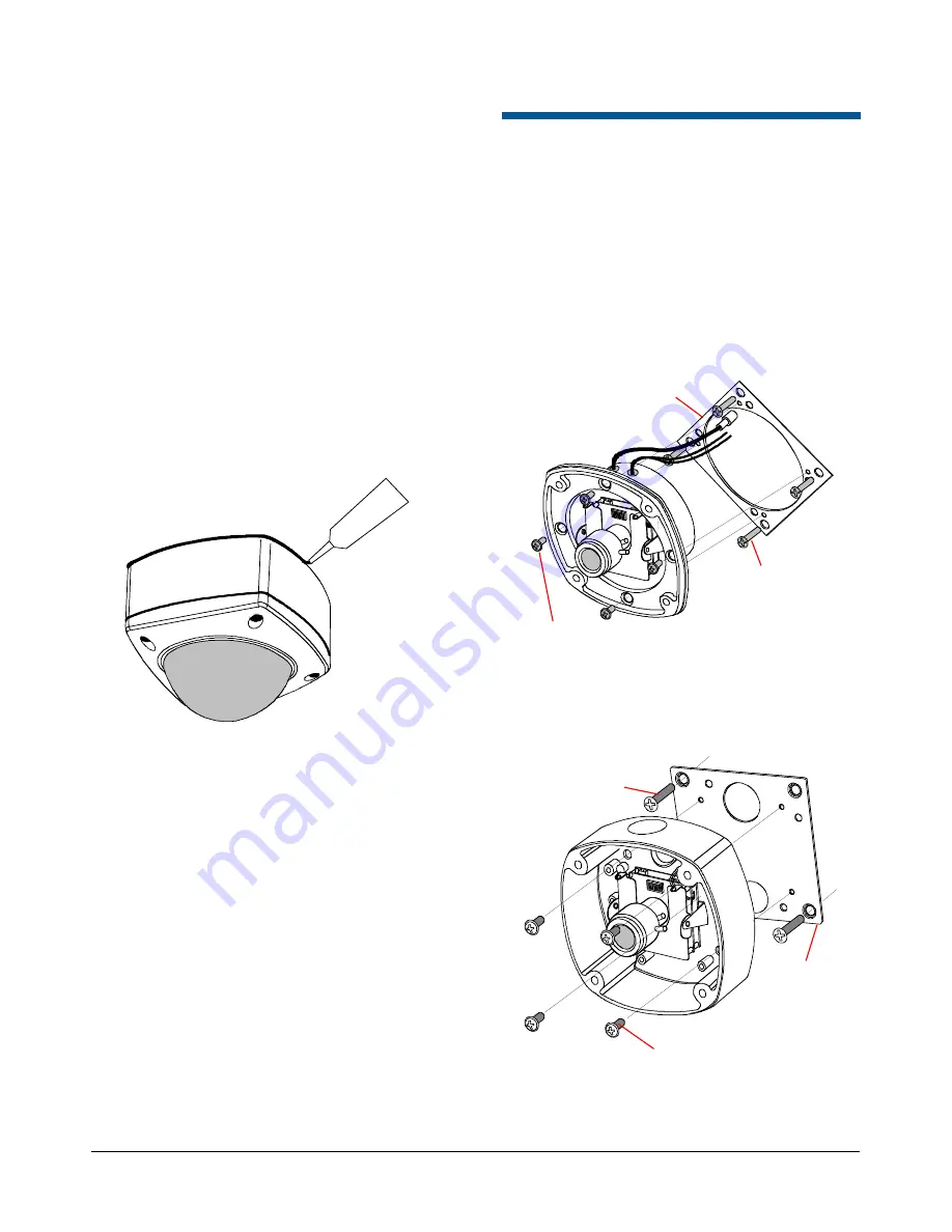
Electrical Box Attachment
Flush Mount
1. Attach the mounting plate to the electrical box
using four 8-32 screws shown.
2. Attach the enclosure to the mounting plate
using four M4 x 8 screws.
Note:
Due to mounting hole locations on the
cover plate, the enclosure will be oriented 45° to
the electrical box.
Surface Mount
Connect enclosure to an electrical box using
screws shown.
M4 x 8 Pan Head
Screws (4x)
8-32 x 0.75 Flat
Head Screws (4x)
Electrical Box
Cover Plate
8-32 x 0.75 Flat
Head Screws (4x)
M4 x 8 Pan Head
Screws (4x)
Electrical Box
Cover Plate


