background image

©American Audio® - www.americanaudio.eu                            Encore2000™                               User Manual Page 20 

9.4


M

OUNTING


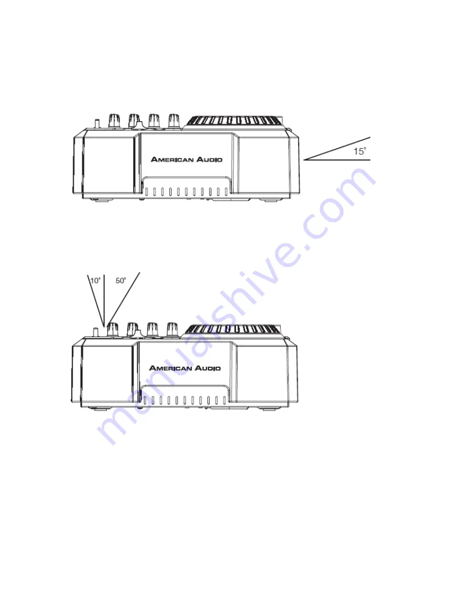
The Encore2000™ will work normally when the unit is mounted with the front panel within 
15 degrees of the vertical plane. If the unit is tilted excessively, discs may not be loaded or 
unloaded properly. 


The LCD is designed to be clearly visible within the angles shown in the picture below.  

Mount the unit so that the visual angle is within this range. 


Summary of Contents for encore2000

Page 1: ... American Audio www americanaudio eu Encore2000 User Manual Page 1 F E A T U R I N G ...

Page 2: ...ericanaudio eu Encore2000 User Manual Page 2 Please Note All specifications and improvements to and in the design of this unit and this manual are subject to change at any time without any prior written or published noticed ...

Page 3: ... American Audio www americanaudio eu Encore2000 User Manual Page 3 6122 S Eastern Ave Los Angeles Ca 90040 www americanaudio eu ...

Page 4: ...pport 15 7 Set Up Precautions 16 7 1 Operating Determinations 16 8 Main Features 17 9 Set Up 19 9 1 Checking the Contents 19 9 2 Power Up Sequence 19 9 3 CD R Disc Guidelines 19 9 4 Mounting 20 10 General Functions and Controls 21 10 1 Player Controls 21 10 2 Mixer Controls 25 10 3 Front Panel 27 10 4 Rear Panel 28 10 5 LCD Display Panel 29 11 Internal Menu 32 12 Basic Operations 34 12 1 Loading E...

Page 5: ... Slider 42 13 2 Pitch Bending 43 13 3 Jog Wheel 44 14 Lock Mode 45 15 Relay Playback 46 16 MIDI Mode 47 16 1 MIDI Table 47 17 DVS Setup 50 18 Accessing MP3 Folders 51 19 Mixer Setup 52 19 1 Typical DJ Setup 52 19 2 Typical Balanced Output Set up 53 20 Crossfader Replacement 54 20 1 Replacing How To 54 21 ROHS A Contribution to the Conservation of Environment 55 22 WEEE Waste of Electrical and Elec...

Page 6: ...n Signal Format MP3 128KBPS EQ Flat Iinput Gain Master Fader Maximum 58 23 4 USB Slave Player Section Signal Format MP3 128KBPS EQ Flat Input Gain Master Fader Maximum Deck Mixer SW to Mixer MIDI Set Up Mix Mixer 58 23 5 Recording Playback Line 1KHz 12dBV Input Gain Maximum 58 23 6 MP3 Format 59 ...

Page 7: ...CE TO YOUR AUTHORIZED AMERICAN AUDIO SERVICE DEALER Please carefully read and understand the instructions in this manual thoroughly before attempting to operate this unit These instructions contain important safety information regarding the use and maintenance of this unit Take special care to follow all warning symbols and labels both on the unit and printed in this manual Also Please keep this m...

Page 8: ...R ADJUSTMENTS OTHER THAN THOSE SPECIFIED HEREIN MAY RESULT IN HAZARDOUS RADIATION EXPOSURE THE DEVICE SHOULD NOT BE ADJUSTED OR REPAIRED BY ANYONE EXCEPT PROPERLY QUALIFIED SERVICE PERSONNEL NOTE This unit may cause interference to radio and television reception NOTE This device uses a semiconductor laser It is recommended for use in a room at the following temperature 41 95 F or 5 C 35 C WARNING ...

Page 9: ...table The product may fall causing serious injury to a child or adult and serious damage to the product Use only with a cart stand tripod bracket or table recommended by the manufacturer or sold with the product Any mounting of the product should follow the manufacturer s instructions and should use a mounting accessory recommended by the manufacturer Ventilation Slots and openings in the cabinet ...

Page 10: ...ead in wire to an antenna discharge unit size of grounding conductors location of antenna discharge unit connection to grounding electrodes and requirements for the grounding electrode See Figure 1 Power Cord Protection Power supply cords should be routed so that they are not likely to be walked on or pinched by items placed upon or against them paying particular attention to cords at plugs conven...

Page 11: ...s have fallen into the product If the product has been exposed to rain or water If the product does not operate normally by following the operating instructions Adjust only those controls that are covered by the operating instructions as an improper adjustment of other controls may result in damage and will often require extensive work by a qualified technician to restore the product to its normal...

Page 12: ... the ventilation openings or placed in a built in installation such as a bookcase or cabinet that may impede the flow of air through the ventilation openings Heat The device should be situated away from heat sources such as radiators heat registers stoves or other appliances including amplifiers that produce heat Power Sources The device should be connected to a power supply only of the type descr...

Page 13: ...________ Purchase Notes ____________________________________________________________ Date of Purchase ____________________________________________________________ Dealer Name ____________________________________________________________ Dealer Address _____________________________________________________________ ___________________________________________________________________________ ___________...

Page 14: ...ge that may have occurred during shipping If the carton appears to be damaged carefully inspect your system for any damage and be sure all equipment necessary to operate the system has arrived intact In the event damage has been found or parts are missing please contact our toll free customer support number for further instructions Please do not return the system to your dealer without first conta...

Page 15: ...vides a toll free customer support line to provide set up help and to answer any questions should you encounter problems during your initial set up or operation You may also visit us on the web at www AmericanAudio us for any comments or suggestions Service Hours are Monday through Friday 08 30 to 17 00 GMT 1 Voice 0031 45 546 85 30 Fax 0031 45 546 85 99 E mail service adjgroup com For spare parts...

Page 16: ...e arising condensation of water might damage your device Leave the device switched off until it has reached room temperature 7 1 OPERATING DETERMINATIONS When installing this device please make sure that it is not exposed to extreme heat moisture or dust Do not operate the mixer in extremely hot more than 40 C 104 F or extremely cold less than 5 C 40 F surroundings Keep the unit out of direct sunl...

Page 17: ...Q Start Control Set up your Encore2000 as described in the set up section of this manual After set up is completed load your players By moving the mixer s crossfader from left to right you can start and pause each player s playback functions For example when using the Encore2000 player if your mixer s crossfader is all the way to the left player one is playing player two is in Cue or Pause mode an...

Page 18: ...layer 2 will instantly begin to play You may set Relay to play track to track or disc to disc For more information on this feature see Relay Playback on page 46 c Sleep Mode The Encore2000 s laser and pick up assembly will power down after the desired set time of inactivity when in Pause or Cue mode is reached This will lengthen the life of your motor drive and laser To initialize the player just ...

Page 19: ...WER UP SEQUENCE SIMPLE SYSTEM POWER UP SEQUENCE Turn ON the Encore 2000 Next turn ON your speakers SYSTEM POWER UP SEQUENCE WITH CONNECTED MIXER AMP ACTIVE SPEAKERS OR EXTERNAL DEVICE Turn ON the amp mixer speakers or any external device first Next turn ON the Encore 2000 9 3 CD R DISC GUIDELINES For best CD R Disc playback results in this CD player please follow these guidelines High quality CD R...

Page 20: ...y when the unit is mounted with the front panel within 15 degrees of the vertical plane If the unit is tilted excessively discs may not be loaded or unloaded properly The LCD is designed to be clearly visible within the angles shown in the picture below Mount the unit so that the visual angle is within this range ...

Page 21: ...to prevent accidentally ejecting the disc when in Play Mode 2 Folder Button This button is used to toggle between folders and tracks Press this button to show the folder that is playing in the LCD Pressing and holding this button for at least 3 seconds will activate Repeat Mode 3 Time Button The Time Button will switch the time value described in the Time Meter 50 between Elapsed Playing Time Trac...

Page 22: ...pitch adjustment works with regular CDs only not MP3 CDs Note Pressing this button and turning the Jog Wheel 11 allows you to view the File Name Title Artist and Genre 7 Pitch Percentage Selector Press this button to select pitch range percentages of 4 8 16 and 100 See Adjusting the Pitch Slider s 5 Range on page 43 Note 100 pitch adjustment works with regular CDs only not MP3 CDs 8 Tempo Lock Fun...

Page 23: ...ercentage up to 100 and turning the wheel in the counter clockwise direction can decrease the pitch percentage down to 100 The pitch bend will be determined on how long you turn the jog wheel continuously The jog wheel also controls the scratch effect when the scratch effect is active The jog wheel can also serve as frame search 12 In Out Reloop Buttons In Button This function Cue on the fly allow...

Page 24: ... track This search button allows you to quickly scan forwards through a track Note Hold down either button and use the Jog Wheel 11 to rewind or forward scan at faster speeds 18 Advance Track Folder Buttons and 10 Track Skip Button This button is used to select a track Tapping this button will forward skip to the next track holding down this button will rapidly forward skip through the tracks When...

Page 25: ...switches are used to select the input source assigned to each channel Each channel may only be assigned one input source at a time Note When using deck output mode switching to deck will route the deck source to the mix 22 AUX Input This Aux input is for the use of a MP3 player Input volume will be controlled by the Channel 2 Fader 23 Channel Gain Control This adjustment is used to adjust an audio...

Page 26: ...ction will increase the amount of midrange applied to a channel signal Bass Control This knob is used to adjust the low frequency levels of a channel allowing for a maximum bass gain of 12dB or maximum signal decrease of 30dB Turning the knob in a counter clockwise direction will decrease the amount of bass applied to a channel signal turning the knob in a clockwise direction will increase the amo...

Page 27: ...e sure the cue level is set to minimum before putting a pair of headphones on 31 Cue Level Volume Knob This knob is used to adjust the headphones volume output level Turn the knob in a clockwise direction to increase the headphones volume 32 Master Volume Control This rotary knob is used to control the Master Output Level volume To avoid distorted output try to maintain an average output signal le...

Page 28: ...E INPUT OTHERWISE DO NOT CONNECT TURNTABLES TO THESE JACKS CD players tape decks and other line level instruments may be connected to these jacks The red colored RCA jack represents the right channel input and the white represents the left channel input Input volume will be controlled by the channel 1 fader The channel Source Selector Switch 21 must be in the Line 1 position to monitor any source ...

Page 29: ...alanced Jacks 42 43 Output Mode Switch Mixer The output RCA plugs will be master and record output Deck The output RCA plugs will send a line level signal for Deck 1 and Deck 2 This can be used for an external mixer or soundcard for recording or DVS software use 44 Balanced XLR Master Output Jacks The Master Output includes a pair of XLR Balanced jacks as well as a pair of RCA Unbalanced Jacks 42 ...

Page 30: ...5 for Lock Mode 54 Loop This icon will appear when a loop point is set 55 Reloop Indicator Appears and flashes when a Loop is active 56 Auto CUE This will indicate if the Auto CUE is On or Off Press and hold the SGL CTN Button 4 for 1 second to turn the Auto CUE function on and off 57 Key Indicator This indicator will glow when the touch sensor part of the jog wheel has been touched 58 Character D...

Page 31: ... single indicator is not on the unit is in continuous mode In continuous mode the drive will play all the remaining tracks on the disc 62 Track Indicator This indicator details the current track The number displayed in the track indicator is a direct reference to the track in play pause or cue mode 63 Play Pause Indicator Either the play or pause indicator will glow depending which mode you are in...

Page 32: ...ustment Adjustment range is 20 20 Increase or decrease the sensitivity of the jog wheels touch sensor The lower the sensitivity level the more pressure the jog wheel needs 3 Pitch Bend Pitch range 1 100 4 CF Curve Cross Fader Curve 0 50 5 MIDI Set Up Mix MIDI or Mixer Mix Ch 1 16 Deck 1 Ch 1 3 5 7 9 11 13 15 Deck 2 Ch 2 4 6 8 10 12 14 16 TAP Hold SW Mode 6 Sleep Time No sleep 5 120 min Set the tim...

Page 33: ...ly shuts off the transport and laser after about 15 minutes when in pause or cue mode This extends the life of your motor drive and laser During sleep mode the display shows the word SLEEP To wake up the player just press the cue or play button the display turns to normal and is ready to receive instructions You can enter the Sleep Time Menu to adjust the sleep time the range is 5 120 minutes Cali...

Page 34: ... stick USB card reader or external hard drive make sure you are correctly lined up with the USB port and connect to the USB port To disconnect a USB drive stop playback and disconnect the USB connection Very important USB Information The Encore2000 will only read MP3 files or WAV files If you are using a SD Card via USB SD Card reader you must remove the USB SD Card reader first to change SD Card ...

Page 35: ... Buttons 18 once will select either the next higher or lower track You can hold down the Track Buttons 18 to change tracks continuously at a faster speed If you are using the Track Buttons 18 to select a new track during playback a track is already in play mode the new track you selected will immediately begin playback as soon as the search operation is completed Tapping the reverse track button w...

Page 36: ... 13 was pressed Pressing the Play Pause Button 13 will switch between play and pause modes When the unit is in pause mode the Pause Indicator 63 will show in the LCD Display 20 The blue Play Pause Button LED will also begin to flash repeatedly 12 5 AUTO CUE This function will automatically set a cue point to the first audio point when a CD is loaded The first set cue point will always be the begin...

Page 37: ... a Cue Point on page 37 Once you are in Pause or Cue Mode turn the Jog Wheel 11 to scroll through the track Turning the wheel in a clockwise direction will advance the frame search and turning the wheel in a counter clockwise direction rewinds the frame search When you use the Jog Wheel 11 the monitor headphone level function allows you to hear what you are scrolling through Once you reach your de...

Page 38: ... your desired starting point Once you have found your desired cue point press the Play Button 13 to set your cue point Pressing the CUE Button 15 will now return you to this exact point Note Scratch mode must be inactive for Jog Wheel search mode to work It is best to use the rim of the Jog Wheel You may also use the Search Buttons 17 to set a cue point While a disc is in Pause or Cue Mode use the...

Page 39: ...create a seamless loop between two continuous points of a disc 1 Press Play Pause Button 13 to activate playback mode 2 Press the IN Button 12 This will set the starting point of the seamless loop The IN Button 12 LED will light 3 Press the OUT Button 12 to set the ending point for your loop The IN Button 12 and OUT Button 12 LEDs will immediately begin to flash rapidly indicating the seamless loo...

Page 40: ...r stored loop at any time The IN Button 12 and OUT Button 12 LEDs will indicate a loop is stored in memory and may be played at any time To replay the loop press the Reloop Button 12 The IN Button 12 and OUT Button 12 LEDs will again begin to flash indicating seamless loop mode has been activated and your loop will immediately begin to play LOOP DIVIDE MULTIPLY When a loop is active you can use th...

Page 41: ...D 20 as the current CD total remaining running time this is for CDs only TIME BAR INDICATOR This details the time defined in the Time Meter 50 as a visual bar icon As with the Time Meter 50 this bar is also dependent on the selected time function Remain Elapsed or Total Remain CD only This bar will begin to flash when a track is ending regardless of which time function you are in Use the flashing ...

Page 42: ...l increase or decrease the tracks playback speed or Pitch The maximum pitch percentage manipulation in this function is 100 The Pitch Slider 5 is used to decrease or increase the playback pitch If the slider is moved up towards the top of the unit the pitch will decrease if the slider is moved down towards the bottom of the unit the pitch will increase The Pitch Slider 5 adjustment can be changed ...

Page 43: ...ly not MP3 CDs 13 2 PITCH BENDING Unlike the Pitch Slider 5 adjustment this function will momentarily increase or decrease a tracks speed during playback There are two ways to operate this function with the Pitch Bend Buttons 10 or with the Jog Wheel 11 The maximum pitch bend percentage allowed is 100 The pitch bend function will work in conjunction with the Pitch Slider 5 pitch setting For exampl...

Page 44: ... bend the pitch if a track is in playback mode Rotating the wheel in a clockwise direction will increase your track pitch and rotating the wheel in a counter clockwise direction will slow your track pitch The speed you rotate the Jog Wheel will determine pitch bend percentage For example if the Jog Wheel is continuously turned in a counter clockwise direction the playback speed will steadily decre...

Page 45: ...be locked so that adjustments can be made to the audio levels To lock the player functions proceed as follows To lock the Encore2000 player press the Relay Button 27 for at least 3 seconds When the Encore2000 is locked the Relay Button 27 and the Lock Indicator 53 will flash To unlock the Encore2000 press the Relay Button 27 for at least 3 seconds Note regarding Relay Mode Activate Relay Mode firs...

Page 46: ...ed press the Play Pause Button 13 on one player to begin playback After the first player s single track has ended the second player s track will immediately begin playback Relay FLIP FLOP will continue until you stop it or power is interrupted To relay entire CDs proceed as follows Be sure your players are both in continuous play mode make sure Single Mode 61 does not appear in the LCDs 20 of both...

Page 47: ...s Depending on the software you are using the MIDI may have to be mapped 16 1 MIDI TABLE SW Name Type MIDI MIDI2 TAP Remarks JOG SW ENC 20 20 5F 5F GAIN VR 21 60 TREBLE VR 22 61 MID VR 23 62 BASS VR 24 63 CH FADER VR 25 64 PITCH FADER Pitch Bend VR Pitch Bend 26 SEARCH SW 9 48 SEARCH SW 1 40 TRACK SW 11 50 TRACK SW 15 54 10 SW 5 44 TIME SW 12 51 SGL CTN SW 16 55 OPEN SW 0E 4D PITCH BEND SW 10 4F T...

Page 48: ...evel Meter LEVEL 1B 1 10 CROSSFADER A SW 35 74 MIX CH CROSSFADER B SW 36 75 MIX CH MIC VR 30 6F MIX CH MASTER VR 31 70 MIX CH CUE LEVEL VR 32 71 MIX CH CUEMIX VR 33 72 MIX CH CROSSFADER VR 34 73 MIX CH RELAY SW LED 14 14 53 MIX CH CC ABSOLUTE VR Control Change messages are sent with status 0xBn where n is the channel for the specified CC controller Thus the controller MIDI ID is indicated with the...

Page 49: ...ages are sent with status 0x9n SWITCH On and Off values are 0x7F and 0x00 where n is the channel LED ON OFF LED These messages are used for LEDs Control Change messages are sent with status 0x9n LED On and Off values are 0x7F and 0x00 where n is the channel PITCH BEND Pitch Bend messages are status 0xEn where n is the channel for the specified controller Thus the controller ID is indicated only by...

Page 50: ... the time code CD s to the CD player tray of the Encore2000 Set the Encore2000 Output Mode Switch 43 to Deck route mode then route the Deck1 and Deck 2 Outputs 41 42 to the software s Audio Interface inputs Route the Audio Interface outputs to the Encore2000 s Line 1 and Line 2 Inputs 38 39 and set the Encore2000 s Source Selector Switch 14 to Line Note Please see DVS software user instructions fo...

Page 51: ...the different folders files located on your MP3 disc Press the Folder Button 2 so that the Folder LED lights up The artist and song title should appear in the Character Display 58 and the Folder number will appear in the Folder Indicator 48 Now press the Track Buttons 18 to scroll forward or backwards through the folders ...

Page 52: ...dio eu Encore2000 User Manual Page 52 19 MIXER SETUP 19 1 TYPICAL DJ SETUP This image details a typical DJ Setup consisting of a microphone MP3 player CD players and a tape deck Note Turntables cannot be connected to the Encore2000 ...

Page 53: ...ypical stereo output layout Note the use of the Balanced XLR Jacks on both the mixer and the amplifier Always use the balanced output jacks whenever possible The balanced output jacks should always be used for cable runs in excess of 15 feet Using the balanced jacks will ensure a clean signal throughout the entire audio system ...

Page 54: ... two outside screws on each side that hold the cross fader assembly in place Gently remove the crossfader assembly from its seated position You may need to wiggle the crossfader slightly to remove it After removing the crossfader assembly disconnect the ribbon cable that attaches the cross fader to the PC board Grasp the crossfader by its base and pull the ribbon cable by its connector not the act...

Page 55: ...electronics we have around us in our households or at work As manufacturers of products of the brands of AMERICAN AUDIO AMERICAN DJ ELATION Professional and ACCLAIM Lighting we are obligated to comply with the ROHS directive Therefore as early as two years prior to the directive coming into force we started our search for alternative environmentally friendly materials and manufacturing processes W...

Page 56: ...evelop a common system of waste management Thereby we can ensure professional and environmentally friendly scraping and recycling program As manufactures we are part of the German system of EAR and we make our contribution towards it Registration in Germany DE41027552 That means that products of AMERICAN DJ and AMERICAN AUDIO can be left in the collection points free of charge and they will be use...

Page 57: ...ER FADER MAXIMUM Output Level 8dBV 2 51V 2dB TCD 782 TRK2 Deck Mixer SW to Mixer 2dBV 794mV 2dB TCD 782 TRK2 Deck Mixer SW to Mixer T H D NOISE Less than 0 04 TCD 782 TRK2 W 20KHz LPF A Weighted Deck Mixer SW to Mixer Frequency Response 17 20KHz 0 2dB TCD 782 TRK2 3 7 Deck Mixer SW to Mixer S N Ratio More than 81dB TCD 782 TRK2 8 W 20KHz LPF A Weighted Deck Mixer SW to Mixer Channel Separation Mor...

Page 58: ... H D NOISE Less than 0 04 TCD 782 TRK2 W 20KHz LPF A Weighted Deck Mixer SW to Mixer S N Ratio More than 81dB TCD 782 TRK2 8 W 20KHz LPF A Weighted Deck Mixer SW to Mixer LR Separation More than 75dB 1KHz TCD 782 TRK2 9 11 W 20KHz LPF A Weighted Deck Mixer SW to Mixer 23 4 USB SLAVE PLAYER SECTION SIGNAL FORMAT MP3 128KBPS EQ FLAT INPUT GAIN MASTER FADER MAXIMUM DECK MIXER SW TO MIXER MIDI SET UP ...

Page 59: ... coding at sampling rates of 32 44 1 and 48kHz MPEG 2 Layer 3 standard ISO IEC 13818 3 which provides for similar coding at sampling rates of 16 22 05 and 24 kHz MPEG 2 5 Layer 3 standard which provides for similar coding at sampling rates of 8 11 025 and 12 kHz 32 40 48 56 80 96 112 128 160 192 224 256 320 kbps Xing VBRI VBR 32 40 48 56 64 80 96 112 144 160 Kbps Xing VBRI VBR 32 40 48 56 64 80 96...

Page 60: ... youtube com adjlighting American Audio World Headquarters 6122 S Eastern Ave Los Angeles CA 90040 USA Tel 323 582 3322 Fax 323 582 3311 Web www AmericanAudio us E mail info americanaudio us American DJ Europe Junostraat 2 6468 EW Kerkrade Netherlands service adjgroup eu www americandj eu Tel 31 45 546 85 00 Fax 31 45 546 85 99 ...

Reviews: