background image


19 

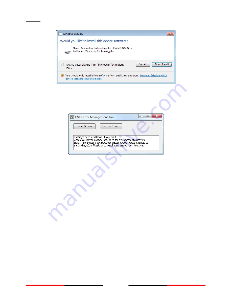
Step 2: A security reminder appears and asks for your confirmation. Click Install to   

proceed. 


Figure 12 


USB Driver Installation (2) 


Step 3: Driver installation is completed. Close the window directly using the close   

window icon. 


Figure 13 


USB Driver Installation (3) 


2.9


Configuration Software Installation 

Install the AMEC WideLink R150GE Configuration Software from the CD-ROM by 
following the on-screen instructions. 
 

Summary of Contents for WideLink R150GE

Page 1: ...USER MANUAL AIS Network Receiver WideLink R150GE...

Page 2: ......

Page 3: ...ance with the requirements as defined in IEC 60945 iv Disposal Instruction Do not dispose of this device with unsorted waste Improper disposal may be harmful to the environment and human health Please...

Page 4: ...igorous demands of industrial marine environment With proper installation and use the equipment will serve loyally and reliably at its optimum For sales services and technical supports please contact...

Page 5: ...Power Supply 18 2 8 USB Driver Installation 18 2 9 Configuration Software Installation 19 3 CONFIGURATION SETTINGS 20 3 1 Connecting the Receiver to your PC 20 3 2 Baud Rate Setting 21 3 3 GPS Settin...

Page 6: ...IS Targets 34 6 SPECIFICICACIONS 35 6 1 Product Specifications 35 6 2 Dimensions 36 7 TROUBLESHOOTING 37 7 1 WideLink R150GE 37 7 2 Wi Fi 37 8 ABBREVIATIONS 39 9 FCC INTERFERENCE STATEMENT 40 FCC RF R...

Page 7: ...fixed server IP via TCP IP and UDP IP protocol It s also possible to display received AIS targets locally on a screen or PC WideLink R150GE has NMEA 0183 RS 232 Ethernet and USB interfaces which make...

Page 8: ...8 1 2 Equipment in the Box Please contact your supplier immediately if there is any item missing Power Adapter is an OPTIONAL item...

Page 9: ...9 1 3 External Connections...

Page 10: ...senger ships It transmits typically on 12 5 watt output power AIS Class B provides limited functionality and is intended for non SOLAS commercial vessels and recreational vessels It transmits typicall...

Page 11: ...rom class A AIS device Type of Message Data Details Static Data Maritime Mobile Service Identity MMSI number IMO number Call sign and name Type of ship Length and beam GPS Antenna location Voyage Rela...

Page 12: ...is not recommended installing the device in a location that will be subject to spray or water submersion The device should not be installed inflammable or hazardous locations such as near a fuel tank...

Page 13: ...13 2 2 Mounting Instructions Figure 2 Mounting Instructions 1 Figure 3 Mounting Instructions 2 Wall Mounting flat surface Platform Mounting...

Page 14: ...rgely decided by line of sight distance the VHF antenna should be placed as high as possible and at least 5 meters away from any constructions made of conductive materials Figure 4 VHF Antenna Locatio...

Page 15: ...ner wires and impair overall the performances Each coaxial cable should be set up separately and can only be set up in a single cable tube Insulation on connector port of the coaxial cable should be c...

Page 16: ...t baud rate is 38400 Use the provided configuration utility to change the baud rates The figure below describes how to wire your AIS receiver with NMEA 0183 device Figure 7 NMEA 0183 Wiring Instructio...

Page 17: ...GE to devices such as industrial machines and scientific instruments WideLink R150GE RS 232 is a standard female connector and the pin definition is defined in below table Figure 9 RS 232 Connector Pi...

Page 18: ...ative terminals and ground Figure 10 Power Supply Connection 2 8 USB Driver Installation Your PC needs to install the USB driver in able to connect the AIS Receiver Locate the USB driver in the CD ROM...

Page 19: ...B Driver Installation 2 Step 3 Driver installation is completed Close the window directly using the close window icon Figure 13 USB Driver Installation 3 2 9 Configuration Software Installation Instal...

Page 20: ...e settings Internal GPS Enable Disable internal GPS antenna Network Network configuration for additional details see Chapter xx Restore Restore the device to factory default settings Diagnostics Syste...

Page 21: ...Device to apply the new the setting The default is set at 38400 bauds Figure 15 Baud Rate 3 3 GPS Setting An integrated GPS receiver is also built in into WideLink R150GE The integrated GPS receiver a...

Page 22: ...ersion and WideLink R150GE IP Address is also shown for diagnostic and configuration purposes To configure WideLink R150GE network properties click on the link Go to Network Configuration Figure 17 Ne...

Page 23: ...none no password are needed The default credentials can be changed at Network Settings by referring to section 4 2 of this manual Connect to WideLink R150GE via Ethernet Ensure WideLink R150GE is powe...

Page 24: ...24 4 1 Network System Status The System Status provides a summary of WideLink R150GE Network parameters that are currently configured into the unit Figure 19 System Status...

Page 25: ...for the device or leave as it is to accept the default name The device name identifies the WideLink R150GE unit among other network devices in the area Administrator 1 Account type a new account name...

Page 26: ...ystem Configuration IP Settings The IP Settings page appears 2 Verify that the IP Network Setting is to obtain the IP address from DHCP server or set to static IP address 3 When the Specify and IP add...

Page 27: ...ration Figure 22 Network Configuration Access Point Mode Under this mode your WideLink R150GE will act as the main wireless host WideLink R150GE is the main access point to all connected wireless and...

Page 28: ...become a wireless client to another Access Point or wireless router The Wireless Client Mode is useful when you want to access internet and AIS data simultaneously Under this mode your WideLink R150G...

Page 29: ...Setting Description Protocol Establish yours prefer network protocol by choosing TCP or UDP connection Network Mode Server is a listening port when is set to server mode Client is a send port when is...

Page 30: ...ckup Restore Settings page appears Save a Copy of Current Settings by backing up your settings it will preserve important settings for future use Restore Saved Settings from A File to restore previous...

Page 31: ...the firmware upgrade Once the firmware is upgraded successfully the device will reboot automatically Figure 25 Firmware Upgrade 4 3 3 System Reset If you encounter WideLink R150GE network issues you...

Page 32: ...ction how to connect your AMEC AIS Receiver to your Macintosh MAC computer and display the received AIS Targets in OpenCPN can be found on the CD attached as well as at http www alltekmarine com suppo...

Page 33: ...d off Error Flashing Red A system error is detected AIS Rx Flashing Green Receiving of AIS message on either AIS Channel 1 or Channel 2 GPS Steady Green GPS Satellite has been acquired Ethernet Steady...

Page 34: ...nformation on PC The application displays AIS targets on a base line map and their dynamic and static information regulated by IMO For professional users we recommend the use of AMEC NaviPro ECS or ot...

Page 35: ...tion Greater than 1 5W Less than 6W LED INDICATION WideLink R150GE Power Error AIS Rx GPS Ethernet Wi Fi INTERFACE GPE Antenna Connector TNC Female VHF Antenna Connector SO 239 Female NMEA 0183 RS 422...

Page 36: ...nch Size in mm H 50 mm 1 96 inch Weight 450g Cable Length Power Cable 1 meter USB NMEA 80 centimeters Ethernet 1 meter CERTIFICATION CE FCC 6 2 Dimensions Applicable to WideLink R150GE model Figure 29...

Page 37: ...gin Password Launch WideLink R150GE Configurator utility Go to Configuration Restore Check Network Settings Clink on Program Device The system will revert to factory default 7 2 Wi Fi 1 What can I do...

Page 38: ...using the same frequency band may interfere with the router s 2 4GHz Wi Fi transmission To improve Wi Fi signal strength you may try the following solutions Ensure the Wi Fi antenna is properly attac...

Page 39: ...Time of Arrival GPS Global Positioning System IMO International Maritime Organization MMSI Maritime Mobile Service Identity SOG Speed Over Ground SRM Safety Related Message SSID Service Set Identifier...

Page 40: ...p For product available in the USA Canada market only channel 1 11 can be operated Selection of other channels is not possible This device complies with Part 15 of the FCC Rules The operation is subje...

Page 41: ...roduct failure Any products returned must be securely packaged and sent pre paid and insured to AMEC or to an AMEC certified service agent All products returned must be accompanied by a copy of the or...

Page 42: ...42 NOTE...

Page 43: ......

Reviews: