


20 Gear Drive, Plymouth Industrial Park, Terryville, CT 06786 page: 27 of 49
Tel: (860) 585-1254 Fax: (860) 584-1973 Web: www.amci.com
2600-13 Press Control Module
MicroLogix 1500 & CompactLogix Resolver Module
Revision 2.1
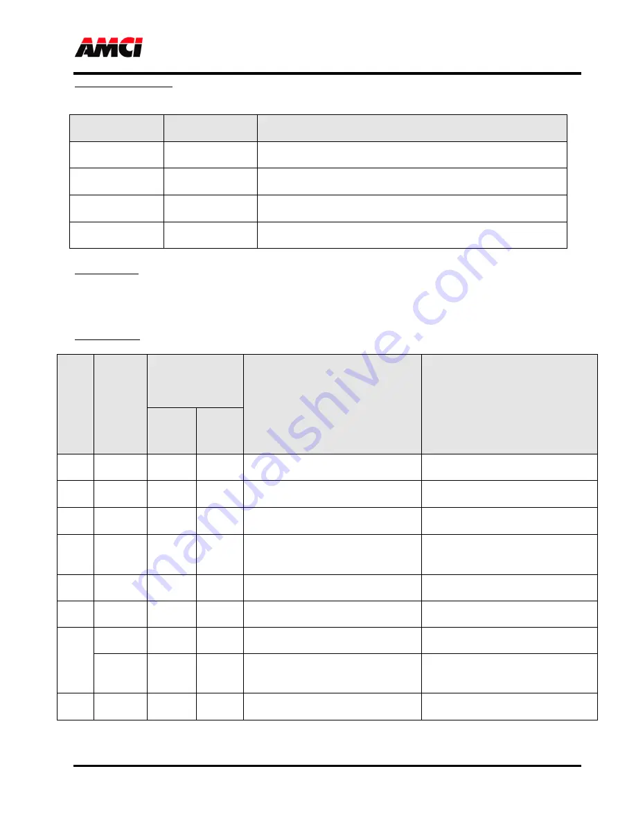
Override Input Value: The bits in this word are combined with the bits in the Override Input Enable Bits to
simulate the Physical Inputs on or off. Bit 0 = Input 16, Bit 1 = Input 17 … Bit 15 =
Input 31. For Example
Override Input
Enable Bit
Override Input
Value
Result
0
0
The state of the Input on the connector is used by the 2600-13
module.
0
1
The state of the Input on the connector is used by the 2600-13
module.
1
0
The 2600-13 module considers the corresponding input to be
inactive.
1
1
The 2600-13 module considers the corresponding input to be
active.
Virtual Inputs: These bits give the PLC control over the 2600-13 module’s Virtual Inputs, which are defined
as inputs 0 to 15. The virtual inputs have no physical presence. These the bits, and therefore
the state of the inputs, are directly controlled by the ladder logic program Bit 0 = Input 0, Bit 1
= Input 1 … Bit 15 = Input 15.
Get Attributes: The value entered in these words controls what data is transferred to input words 6 and 7.
A
tt
ri
b
u
te
N
u
m
b
er
A
tt
ri
b
u
te
D
a
ta
Displayed in
Status Word 0
of
PLC Input
Registers
Displayed in
Word 6
of
PLC
Input Registers
Displayed in
Word 7
of
PLC
Input Registers
Bits 6,5
Bits
4..0
0
Not used
00
00
2600-13 modification read from the
module;
Firmware version (MSB) + revision
(LSB) number;
1
Not used
00
01
Physical Output
state without
inversion or override;
Physical Input
state after applying
override and inversion;
2
Not used
00
02
Virtual Outputs
calculated from the
Limit Switch Setpoints;
Physical Outputs
calculated from
the
Limit Switch Setpoints;
3
Not used
00
03
The last valid position accounting
for the programmed
Resolver
Rollover Counts;
12-bit
Resolver Position
from the
front connector;
4
Not used
00
04
+/- signed
Turn Count
MSW (1000s
places);
+/- signed
Turn Count
LSW (1s,
10s and 100s places);
5
Not used
00
05
=0 (reserved);
=0 (reserved);
6
32
00
06
Global Preset
Value;
Global Offset
Value;
Output
xx
(0..31)
10
xx
Preset
Value for
Output Point
xx
;
Offset
Value for
Output Point
xx
;
7
Input xx
(0..31)
11
xx
(Rising) Position
at which the
Input
Point
xx
changed from 0 to 1;
(Falling) Position
at which the
Input Point
xx changed from 1 to 0;


