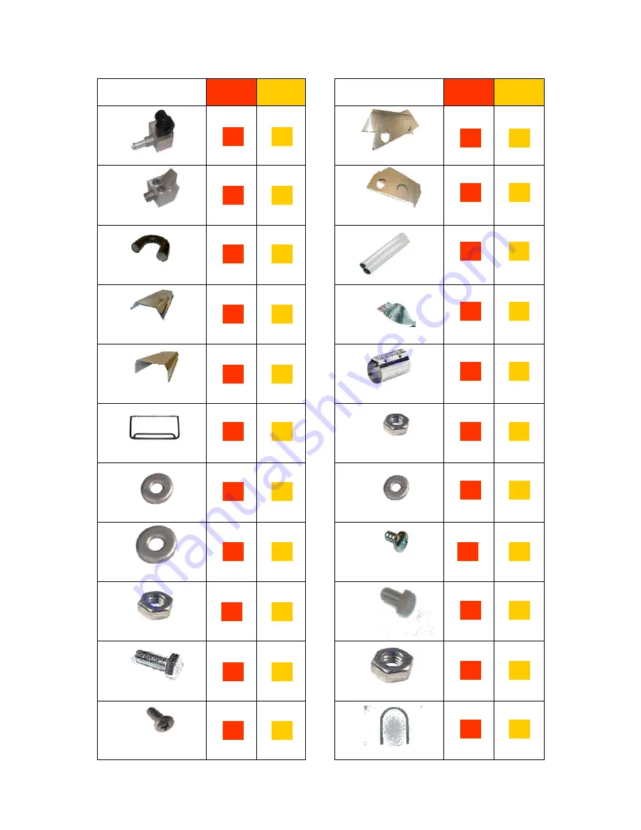
Ambirad Vision Range VSXUS Owner'S Manual Download Page 16

16 

COLOUR CODE 

VSX90 

VSX140 


U Bend 

Inner  
Reflectors 

Outer 
Canopy 

Heat 
Exchanger 

1x 

1x 

1x 

1x 

COLOUR CODE 

VSX90 

VSX140 


1x 

1x 

2x 

3x 

2x 

3x 

Inner 

End Caps 

Outer  
Canopy 
End Caps 

Tubes 

Turbulators 

Couplers 

2x 

2x 

2x 

2x 

2x 

2x 

2x 

3x 

2x 

2x 

Brackets 

3x 

4x 

M4 
Full Nut 

1x 

2x 

Burner 

M6 
Mudwasher 

M6 
Washer 

M6 
Full Nut 

M4 x 10 
Pozi Setpin 

No.5 
Torque 
Screw 

M4 
Washer 

M6 x 15 
Setpin 

M8 
Full Nut 

M8 U Bolt 

16 

10 

12 

13 

16 

14 

22 

M6 x 35 
Setpin 

2.2  Identification check list


Summary of Contents for Vision Range VSXUS

Page 1: ... installation adjustment alteration service or maintenance can cause property damage injury or death Read the installation operating and maintenance instructions thoroughly before installing or servicing this equipment ...

Page 2: ...ulations are adhered to at the mounting heights specified PLEASE READ this document prior to installation to familiarize yourself with the components and tools you require at the various stages of assembly All Dimensions shown are in inches unless otherwise stated The manufacturer reserves the right to alter specifications without prior notice Welcome to the new range of high efficiency AmbiRad VS...

Page 3: ...n the specific bill of lading 1 3 Heater Suspension Attachment to the heater support lugs should be made by a speed link D shackle or in the case of drop rods a closed formed hook The hanging attachments to overhead steelwork etc must be purpose made to good sound engineering practice or of a proprietary type fixing They must be adequately fixed and designed to carry the whole weight of the heater...

Page 4: ... Drop rod with formed hook n b hook or eyebolt must be closed tight after installation Alternative method of suspending U tube and linier type heaters IMPORTANT THE HEATER SHOULD SLOPE DOWNWARDS TOWARDS THE RETURN BEND BY APPROX 10mm FOR BOTH HORIZONTAL AND WALL MOUNTED INSTALLATIONS 15 max VSX models Vertical orinclined suspension on this plane is acceptable Ensure that there is adequate provisio...

Page 5: ...ances to combustibles VSXUS C1 B E A C2 or C3 D1 or D2 B B A VSX models Minimum clearance from the heater must be maintained from vehicles parked below heater In all situations clearances to combustibles must be maintained Signs should be posted in storage areas to specify maximum stacking height to maintain required clearance to combustibles Refer to mounting clearance tables WARNING IMPORTANT Th...

Page 6: ...making a gas connection to the heater not to apply excessive turning force to the internal controls Depending on the specific installation the flexible gas hose may be routed to the gas cock at any of the following angles in relation to the burner Care must be taken to observe the minimum pipe bend diameter minimum 10 maximum 14 pipe expansion distance minimum 1 maximum 3 The correct installation ...

Page 7: ...s per thermostat for zone control of the heated area Control Panels are not A G A CSA design certified Where alternative m a n u f a c t u r e s controls are used please refer to their instructions for their siting and installation details Table 3 Gas Supply Pressures Gas Type Natural Gas Required Gas Pressure in W C 7 0 Maximum Supply Pressure in W C 14 0 Gas Supply Connection N P T internal thre...

Page 8: ... YELLOW If any of the original wire as supplied with the appliance must be replaced it must be replaced with wiring material having a temperature rating of at least 220 F 105 C Heater 1 Heater 2 Heater 3 Heater 4 Heater 5 Heater 6 Double pole insulator adjacent to each heater Thermostats Zone 1 Zone 2 Zone 1 Zone 2 Time switch Manual switch L N G Frost Thermostat 120v 1ph 60Hz Two Zones Double pol...

Page 9: ... or use an approved insulating thimble Standard vent terminals must extend at least 6 from the wall and at least 24 from any combustible overhang Protect the building material from degradation by the vent gasses Vent joints should be sealed and secured using at least 3 sheet metal screws Should condensation occur the vent should be shortened or insulated The terminal should be at least 3ft away fr...

Page 10: ... REFLECTOR FLEXIBLE DUCT HEAT EXCHANGER 4 O D HIGH TEMP 4 O D PIPE CLAMPS MAX LENGTH 25 0 WITH 2 90 LONG RADIUS BENDS 90 BEND INLET WITH 6 SEAL JOINTS WITH SILICONE OR DUCT TAPE WALL BIRD SCREEN TERMINAL 36 MIN CENTERS Figure 8 a Fresh Air Ducted Intake Figure 8 b Wall Terminal Intake Kit Option 2 For ducted air and products of combustion to ventilated area please refer to Figure 8 f Option 3 For ...

Page 11: ...ADAPTER REFLECTOR CLAMPS FLEXIBLE DUCT 4 O D HIGH TEMP SEAL JOINTS WITH HIGH TEMPERATURE SILICONE 6 COLLAR SEAL JOINTS WITH HIGH TEMPERATURE WALL 4 O D MAXIMUM LENGTH 12 0 6 O D MAXIMUM LENGTH 25 0 PLUS A MAXIMUM OF 2 x 90 BENDS SUPPLIED BY OTHERS SILICONE INLET WITH BIRD SCREEN 36 MIN CENTERS REQUIRED ONLY FOR 6 DIA VENT 4 TO 6 DIA ALUMINIUM ADAPTER REFLECTOR CLAMPS FLEXIBLE DUCT 90 BEND HEAT EXC...

Page 12: ...ith no vent the ventilation instructions detailed in section 1 8 must be applied Ducted air must be used in locations where there is airborne dust or where there is a polluted atmosphere e g Chlorinated Vapours Maximum length 25ft Minimum diameter 4in Maximum no of bends 2 Option 1 Figure 8 e Forced Burner with Heat Exchanger Standard Vent For vented products of combustion and no ducted air Refer ...

Page 13: ...heaters are installed with no vent the ventilation instructions detailed in section 1 8 must be applied Ducted air must be used in locations where there is airborne dust or where there is a polluted atmosphere e g Chlorinated Vapours Maximum length 25ft Minimum diameter 4ins Maximum no of bends 2 Option 2 Figure 8 f Forced Burner with Heat Exchanger No External Venting For ducted air and products ...

Page 14: ...the ventilation instructions detailed in section 1 8 must be applied Ducted air must be used in locations where there is airborne dust or where there is a polluted atmosphere e g Chlorinated Vapours Maximum length 25ft Minimum diameter 4ins Maximum no of bends 2 Option 3 Figure 8 g Forced Burner with Heat Exchanger with Concentric vent For vented products of combustion and ducted air via concentri...

Page 15: ...17 VSXUS90 2576T 3133 201676 12 2 Assembly Instructions PLEASE READ this section prior to assembly to familiarise yourself with the components and tools you require at the various stages of assembly Carefully open the packaging and check the contents against the parts and check list The manufacturer reserves the right to alter specifications without prior notice Please ensure that all packaging is...

Page 16: ...r End Caps Outer Canopy End Caps Tubes Turbulators Couplers 2x 2x 2x 2x 2x 2x 2x 3x 2x 2x Brackets 3x 4x M4 Full Nut 1x 2x Burner M6 Mudwasher M6 Washer M6 Full Nut M4 x 10 Pozi Setpin No 5 Torque Screw M4 Washer M6 x 15 Setpin M8 Full Nut M8 U Bolt 8 6 16 6 10 6 8 12 4 6 4 7 7 13 2 16 8 14 4 22 M6 x 35 Setpin 2 2 Identification check list ...

Page 17: ...eciding which end will have the burner mark out the position of the first bracket as shown in the assembly drawings section Slide brackets over tubes as shown 1 2 4 Step by step installation 2 4 1 TUBES TURBULATORS 2x 2x 3 D0 NOT tighten any of the nuts at this stage Locate and insert turbulator s into tube s ensuring the correct length and quantity are inserted into the correct tube See assembly ...

Page 18: ...lectors supplied all have the same hole positions however each end reflector should be positioned with the holes for the end caps position arrowed outermost Starting at the burner end slide the reflectors through the brackets until they are all roughly in position along the heater referring to the assembly diagram showing overlaps Measure the distance between the end of the burner end tubes the ce...

Page 19: ...s together using end elongated holes in each 4x 4x 9 At this stage all the U bolts should be fully tightened Using M4 setpins washers fix the cut out end cap beneath the reflector profile at the burner end with the flanges facing outwards Locate M4 pins washers nuts into holes in overlapping reflectors as shown 1x 2x 2 4 4 END CAPS Using M4 setpins washers fix the blank end cap beneath the the ref...

Page 20: ...ner and heat exchanger be assembled once the heater has been installed in the roof space Locate 6 off No 5 torque screws Position the blank canopy end cap with the end cap flanges facing inwards beneath the canopy profile at the U bend end fix with screws Repeat procedure for cut out canopy end cap again ensuring the flange faces inwards Adjust canopies so that the holes on top align with each oth...

Page 21: ...the technical dimensional details of the VSXUS range of heaters Figure 9 VSXUS Heater Assembly VSXUS90 3400 TURBULATOR INSERT 201705 Please note the heater type length and reference number from the delivery advice note before identifying the correct model drawing ...

Page 22: ...22 VSXUS140 2600 TURBULATOR 976 TURBULATOR 2600 TURBULATOR ...

Page 23: ...23 Figure 10 VSXUS Heater Breakdown 3 module VSXUS140 shown ...

Page 24: ... a satisfactory pressure condition has been established the ignition sequence will commence The spark ignition will be energized producing a spark at the ignition electrode The gas solenoid valve will at the same time be energised and the burner on lamp will illuminate If the ignition is successful the flame is detected by the flame sensing probe and the burner on lamp will remain on If ignition i...

Page 25: ...n through its start up sequence and ignite Turn off power and check that all components are securely fastened Has the burner lit Check operation on flame failure Check gas pressure Check gas pressure Close control housing Leave the instructions with a responsible person Check operation of air pressure switch should attempt to relight and if the gas valve has been left off lock out should occur ind...

Page 26: ...iver Leather Faced Gloves Spanner 4 1 Tools Required The following tools and equipment are advisable to complete the tasks laid out in this manual Suitable alternative tools may be used Large Adjustable wrenches for fitting of Gas Flex A Ignition Controller B Gas Valve C Burner On Amber Neon D Power On Red Neon E Injector F Burner Tube G Pepperpot Head H Ignitor Assembly I Jet Carrier J Combustion...

Page 27: ...hanger and remove the flexible hose from the burner Step 5 Slacken the set screw on the burner support casting to enable the burner to be removed from the radiant tube Step 6 Remove the burner and position the burner in a safe area to prevent the burner or components attached to the burner from falling to the ground 4 4 Burner Gas Injector Servicing Step 1 a Remove the burner support casting and g...

Page 28: ... replaced ensuring the 5 holes on the outer ring are aligned alongside the probes Step 3 The condition of the igniter assembly can be checked for deterioration However we advise replacement at each service to ensure continued reliability Detach the electrode assembly from the burner head by removing the two screws and separating the igniter lead connectors Step 4 Refit the electrode assembly and e...

Page 29: ... brush Step 6 Remove any dust from fan scroll and from around the motor Step 7 Ensure the impeller rotates freely Step 8 Refit components 4 7 Radiant Tube Servicing Step 1 Brush any dust from the exterior of the tubes Step 2 Inspect the fan and burner tubes visually If the tubes appear clean skip to servicing the reflector Step 3 Remove the U bend Step 4 Withdraw the turbulators from the appliance...

Page 30: ...rvicing The condition of the reflectors should be noted If necessary the reflectors can be cleaned with a mild detergent This can significantly improve the efficiency of the appliance 4 10 Sweeping of Vent Inspect the fresh air inlet duct and vent to ensure they are free from any blockage or obstruction The air inlet terminal and vent terminal should be inspected to ensure they are not liable to o...

Page 31: ...ol reg Part No Description See section 1 11 Injector 200358 Burner Tube Item 201284 Ignitor Assembly Part No Description 200988 Pepperpot Head Item 201676 Pressure Switch 2181 Amber Neon Burner On 2176 Red Neon Mains On 200420 Jet Carrier 2560 1 2576T Combustion Fan 140 90 201488 Gasket Set 900225 2 900225 3 900225 1 Cables Spark Electrode black Rectification lead purple Earth lead green yellow 20...

Page 32: ...cuum switch pull in Check 1 Wiring harness plugs 2 Vacuum switch operation 3 Replace fan Is the burner sparking Does the gas valve open Check 1 Ignition controller 2 Replace gas valve Check 1 Vacuum switch tubes 2 Emitter tubes air inlet vent for obstructions 3 Operation of vacuum switch 4 Replace fan NO YES Check 1 Ignition controller 2 Wiring harness 3 Amber neon faulty Check 1 Burner inlet pres...

Page 33: ... Fit new burner controller Step 6 Refit leads Step 7 Test product and close access door 7 2 Air Pressure Switch Replacement Step 1 Open left hand door Disconnect the two silicone impulse tubes Step 2 Remove the two screws as shown below Step 3 Remove electrical connections The air pressure switch can now be removed Step 4 Fit the new air pressure switch ensuring the impulse tubes are connected as ...

Page 34: ...er head can now be detached by disconnecting the impulse tube and the burner head wiring Step 6 Detach the two screws holding the front of the gas valve Step 7 Remove the four screws holding the rear burner plate in position Step 8 Remove the rear plate Step 9 The jet carrier gas inlet and wiring harness can now be detached from the gas valve Step 10 The two screws retaining the gas valve can then...

Page 35: ...35 THIS PAGE HAS INTENTIONALLY BEEN LEFT BLANK ...

Page 36: ...ff 8 3 Servicing 1 To ensure continued efficient and safe operation it is recommended that the heater be serviced regularly by a qualified person every year in normal working conditions but in exceptionally dusty or polluted conditions more frequent servicing may be needed 8 User Operating Instructions Document reference number US VS 19 0710 AmbiRad is the manufacturer of a series of tubular infra...

Reviews: