7/30
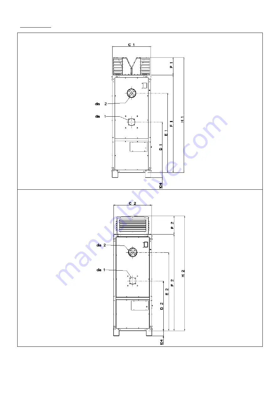
2.2 Dimensions
Vertical heater range
Figure 1a : unit with discharge nozzle
Front view
Figure 1b : unit with discharge plenum
Page 1: ...Leave it with the user or attached to the appliance or gas service meter after installation WARNING Improper installation adjustment alteration service or maintenance can cause property damage injury...
Page 2: ...ectrical Connection 3 3 Ventilation Requirement 4 0 Installation 4 1 Location 4 2 Heater Clearances 4 3 Flue 4 4 Nozzled Heaters 4 5 Ducted Heaters 4 6 Filters 4 7 Controls 5 0 Commissioning 5 1 Pre C...
Page 3: ...ered gas installers 1 1 7 Warning Unauthorised modification of this appliance or departure from use in the manner for which it was intended by the manufacturer or installation in a manner contrary to...
Page 4: ...cations Each heater must have its own individual open flue 1 4 2 All cabinet heaters are fitted with a pre tested and set forced draught burner A sequential control box is fitted to each burner to pro...
Page 5: ...0 GS20 GS20 GS20 Minimum gas inlet mbar 17 5 20 17 5 20 17 5 20 17 5 20 17 5 20 17 5 20 17 5 20 17 5 20 17 5 20 17 5 20 17 5 20 17 5 20 pressure ins WG 7 8 7 8 7 8 7 8 7 8 7 8 7 8 7 8 7 8 7 8 7 8 7 8...
Page 6: ...0 39 39 41 45 42 heater nominal F 65 90 52 65 76 67 72 70 70 74 81 76 Sound level 2 for guidance only Flue spigot outside diameter Total absorbed electrical power VCHE HCHE Model FRAME size I II III I...
Page 7: ...7 30 2 2 Dimensions Vertical heater range Figure 1a unit with discharge nozzle Front view Figure 1b unit with discharge plenum Front view...
Page 8: ...8 30 Figure 1c Side view Figure 1d Figure 1e Figure 1f burner mounting flange air inlet air inlet...
Page 9: ...e Figure 2a Side view Figure 2b Front view Remark The fixation eyes 4x dia 22 5 may only be used to put the unit into horizontal position after delivery It is strictly forbidden to use the fixation ey...
Page 10: ...3 2073 2012 2012 inside dia 1 burner inlet 110 110 120 120 140 140 155 155 155 155 H1 2088 2088 2168 2168 2376 2378 2477 2477 2466 2466 H2 2164 2164 2114 2114 2400 2400 2395 2395 2334 2334 K1 K2 35 5...
Page 11: ...appliance and in view when facing the service compartment The isolator must have a contact separation of at least 3 0mm on all poles 3 2 5 The cabinet heaters are foreseen with a control unit supplied...
Page 12: ...re in the zone as this will lead to a hazardous situation whereby the air heater flue will act as a pressure relief 3 3 6 Normally cabinet air heaters which are used in the free blowing mode i e witho...
Page 13: ...ake use of the fixation eyes to suspend the unit When unit is installed as a ducted heater the duct connections must be installed as described in 4 5 3 Ensure the dimensions of inlet outlet duct are t...
Page 14: ...sized in accordance with the diameter appropriate to the appliance flue connection socket Flues must be terminated with an approved terminal fitting Attention ensure that the connection of the flue t...
Page 15: ...for the sizes 140 150 180 and qty 18 for the sizes 215 250 see fig 8 The horizontal louvers may be adjusted to obtain proper deflection and air pattern For safety reasons it is recommended to wear glo...
Page 16: ...16 30 Figure 8 Nozzle plenum DB1 DA1 D A 2 D B 2 Figure 9 Vertical louvres...
Page 17: ...g Duct outlets must be adjusted when necessary to meet the values mentioned in table 9 Table 9 Frame Model Nominal airflow Available outlet static pressure Motor load maximum Motor current normal use...
Page 18: ...be adjusted when necessary to meet the values mentioned in table 9 4 5 5 Ducted air inlet on VCHE HCHE units The unit is designed so that it can be installed with inlet air ducts Vertical units Option...
Page 19: ...556 III 90 120 541 4 end 691 1054 651 1014 541 5 top 541 7 bottom 1201 707 1161 667 541 6 rear 1082 707 1042 667 IV 140 150 180 541 4 end 1082 1201 1042 1161 541 5 top 541 7 bottom 1400 596 1360 556 5...
Page 20: ...ails Filters must be inspected on a regular basis as dirty filters can affect the safe working of the unit For safety reasons it is recommended to wear gloves glasses when inspecting the filters Dirty...
Page 21: ...end 1 standard 2 duct left 3 duct right 4 duct rear Figure 13a Overview of the VCHE options Note When filters option 502 1 are required then the standard air intake panels must be replaced by the pane...
Page 22: ...before commencing then proceed with the following checks a Ensure electrical supply has been switched off b Ensure the gas supply is switched off c Check that the heater has been installed on a suita...
Page 23: ...Then check the following Fan limit stat settings are correct The bi metal strip has not been damaged The bi metal strip casing is not in contact with the heat exchanger body l Adjust temperatures and...
Page 24: ...Same as after 6 months b Heat exchanger inspection and cleaning c Burner maintenance d Main fan and motor e Pulley and belts f Flue system g Control panel and electrical connections h Gas supply conn...
Page 25: ...ave worn excessively then change the whole set immediately DO NOT MIX BELTS OF DIFFERENT AGES OR BATCHES As the belts stretch at a different rate according the batch curing number and age premature fa...
Page 26: ...sure switch Check gas pressure switch Check burner motor Burner starts but goes to lockout Check gas supply Bad earth Main gas cock open Air in gas line Flame probe failure Air pressure switch failure...
Page 27: ...ting Check control box Signal Check main gas actuator Burner lights but will not hold on main flame Insufficient air High inlet Pressure Fan limit stat Air inlets blocked Outlet nozzles closed Duct re...
Page 28: ...ustion chamber CC air deflector 10 fixation plate HE 11 sliding bracket HE 12 over pressure relief panel 13 heat exchanger combustion chamber 14 side air deflectors 15 side inner skins 16 top side pan...
Page 29: ...0 60 75 Contactor 60 61679 D910M5 sizes 90 120 140 150 180 215 Contactor 60 61679 D1210M size 250 60 61703 02 04 size 90 60 61703 04 06 size 120 60 61703 05 09 size 140 60 61703 07010 sizes 150 180 21...
Page 30: ...bility BSEN 50165 Safety of Electrical Equipment BS 5991 Indirect Gas Fired Heaters less than 2MW BS 5440 Part 1 Specification Installation of Flues Part2 Ventilation Requirements of Gas Appliances BS...