


17/30
4.5 Ducted
Heaters
4.5.1
The Ambi-Rad ducted cabinet heater is
designed to be used with discharge ducting.
A positive seal should be made between
any ducting and the air heater. A flexible
connection is desirable to eliminate
transmission of noise and to take account of
thermal expansion.
4.5.2 Consideration
should be given to the
application of duct fittings directly connected
to the appliance. Air outlet elbows,
transitions etc. should be designed to ensure
an unrestricted and turbulent free air flow.
This requirement is to ensure than an even
air temperature is maintained when leaving
the appliance thus eliminating heat
exchanger "hot-spots" and nuisance shut-
down of the burner due to over heating.
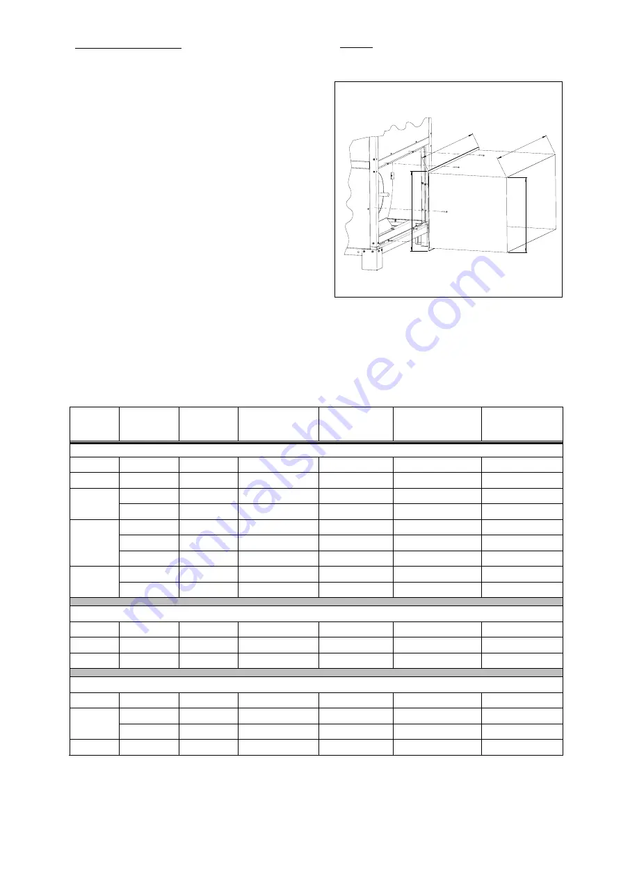
4.5.3
Figures 8 and. 10
illustrate the principle and
the method of fixing duct channels to the
heater
-
ducts must have adequate duct flanges to
fit into the frame structure of the heater
-
the dimensions DA1/DA2/DA3/DA4 refer to
the duct flange; the dimensions
DB1/DB2/DB3/DB4 refer to the duct.
-
duct flanges must be screwed to the frame
structure; holes are provided in the frame
Remark
: fig. 10 shows ducted air inlet fixation – same
fixation method applies for ducted air outlet
Figure 10
DB
4
DB3
DA
4
DA3
Attention must be given to the motor load when
applying discharge ducting. Duct outlets must be
adjusted when necessary to meet the values mentioned
in table 9.
Table 9
Frame Model Nominal
airflow
Available outlet
static pressure
Motor load
(maximum)
Motor current
normal use (*)
Voltage
m³/h Pa
(A)
(A)
(V)
Standard airflow conditions
I
30/40
2500
95
4.00
3.4
230V – 1N
II
50/60/75
5180
130
9.00
7.8
230V – 1N
90
7140
125
3.20
2.3
400V – 3N
III
120
8750
150
5.08
3.7
400V – 3N
140
10500
200
6.60
5.4
400V – 3N
150
11500
215
8.00
7.8
400V – 3N
IV
180
12800
250
8.50
8.4
400V – 3N
215
14100
160
9.00
7.0
400V – 3N
V
250 17330
250 11.50
11.0
400V – 3N
High airflow conditions (when option 403 is applied)
Frame III
90
8750
150
5.08
3.7
400V – 3N
Frame IV 140/150
12800
250
8.50
8.4
400V – 3N
Frame V
215
17330
230
11.50
11.0
400V – 3N
High outlet static pressure conditions (when option 404 is applied)
Frame III
90
7140
205
5.08
3.7
400V – 3N
140
10500
350
8.50
8.4
400V – 3N
Frame IV
150
11500
310
8.50
8.4
400V – 3N
Frame V
215
14100
330
11.50
11.0
400V – 3N
(*)
Current is measured in cold air conditions (heating off) while unit is working at standard air flow. However, measuring motor
current of 10% lower than the figures mentioned in table 9, means that the air flow will be lower and the
∆
T higher. In this case
overheating can occur. To avoid this problem, larger outlets must be provided. In case motor current is greater than the
maximum motor load (mentioned in table 9) duct outlet openings must be decreased so that motor load becomes lower.
We strongly recommend respecting the figures given in table 9.


