background image


Version 1.2  


©Copyright 2017, Ambient LLC. All Rights Reserved. 


Page 17 

polarity. 

5.14


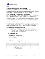
Viewing the Wireless Sensor Channels 

In normal time mode, press the 

UP

 button to view wireless channels 1, 2 and 3.   

 
To automatically scroll through channels 1, 2

and 3, press and hold the 

UP

 button for 2 seconds (the 

beep will sound). The wireless channels will scroll on the screen every 5 seconds. 

5.15


  Syncing and Resyncing the Wireless Sensor 

If  the  sensor  is  synced  to  the  console,  the  console  will  display  the  reception  icon  with  the  signal 
strength 

.   

If the sensor signal is lost, dashes --.- will be displayed in place of temperature. 

 
If  you  lose  synchronization  from  the  remote  wireless  sensor  for  an  extended  period  of  time  or  you 
replace the batteries in the wireless sensor, you may need to resync or reset the sensor to the console.   
 
To resync the sensor(s), press the 

SENSOR

 button in the battery compartment and the sensor display 

will show dashes (--.-). Wait several minutes for resynchronization. 
 
To reset the console, disconnect from AC power and remove the batteries for 10 seconds, then reinsert 
the batteries and reconnect AC power. Alternately, you can press the 

RESET

 button on the back of the 

console. The sensor display will show dashes (--.-). Wait several minutes for resynchronization. 

5.16


Adding Multiple Wireless Sensors 

If you introduce additional sensors into the system, you will need to reset the console.   

1.


Set  the Channel  number on the wireless sensor per  Figure  2. Power down and  up the 

sensor after you have changed the channel number for the change to take effect. 

2.


  Resync the console.    Reference Section 5.15. 

6.


  Specifications 

6.1


Wireless Specifications 


Line of sight wireless transmission (in open air): 150 feet 


Frequency: 433 MHz 


Update Rate: 60 seconds 

6.2


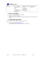
  Measurement Specifications 

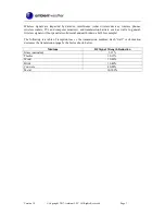
The following table provides specifications for the measured parameters.   
 

Measurement 

Range 

Accuracy 

Resolution 

Indoor Temperature 

32 to 113 °F 

± 2 °F 

0.1 

Outdoor Temperature 

-4 to 140 °F alkaline 
batteries 
-22 to 140 °F Lithium 
e2 Energizer batteries 

± 2 °F 

0.1 

Summary of Contents for ClearView RC-8401A

Page 1: ...m Settings 11 5 2 1 Using the Alarm and Snooze Functions 11 5 3 Projector and Backlight 12 5 3 1 Using the Projector and Backlight 12 5 3 2 Projector Rotation 12 5 3 3 Adjusting Projector Focus 12 5 3 4 Projector Temperature Display 12 5 4 Barometric Pressure Display and Settings 13 5 4 1 Barometric Pressure Units of Measure 13 5 4 2 Absolute Pressure vs Relative Pressure 13 5 4 3 Relative Pressur...

Page 2: ...tatement 20 11 Warranty Information 20 1 Introduction Thank you for your purchase of the Ambient Weather RC 8401A ClearView Projection Radio Controlled Alarm Clock with Barometer Forecast Indoor Temperature and Color Changing Outdoor Temperature The following user guide provides step by step instructions for installation operation and troubleshooting To download the latest full sized manual and ad...

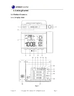
Page 3: ...Version 1 2 Copyright 2017 Ambient LLC All Rights Reserved Page 3 3 Getting Started 3 1Product Features 3 1 1 Display Clock Figure 1 ...

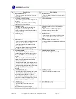
Page 4: ...ds to enter time set mode In time set mode press to step through the different time and date settings 16 PROJECTION On Off Switch Turns the time and temperature projection on or off 6 ALARM Button In normal time display mode Press TIME button to display ALM1 ALM2 Press ALARM to turn on off ALM1 ALM2 Press to stop the current alarm when the alarm is ringing and turn off the alarm and snooze functio...

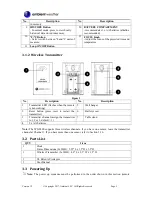
Page 5: ...on 1 Transmitter LED flashes when the remote is transmitting 5 Wall hanger 2 Reset button press reset to restart the transmitter 6 Battery cover 3 Transmitter channel assign the transmitter to 1 2 or 3 default 1 7 Table stand 4 2 x AA batteries Note The WS 8400 supports three wireless channels If you have one sensor leave the transmitter channel at Channel 1 If you have more than one sensor refer ...

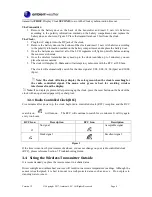
Page 6: ...arch for the time signal at 2 00 8 00 14 00 2pm and 20 00 8pm Note The clock will always display the color green when the clock is searching for the radio controlled signal The mono color green is best for avoiding wireless interference from the display Note If no display is present after powering up the clock press the reset button on the back of the clock with an open ended paper clip or sharp t...

Page 7: ...d transmission barriers such as walls In general wireless signals will not penetrate solid metal and earth down a hill for example The following is a table of reception loss vs the transmission medium Each wall or obstruction decreases the transmission range by the factor shown below Medium RF Signal Strength Reduction Glass untreated 5 15 Plastics 10 15 Wood 10 40 Brick 10 40 Concrete 40 80 Metal...

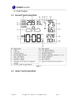
Page 8: ...perature Alert 3 Weather Forecast 12 Min Max indicator 4 History Mode indicator 13 Wireless temperature channels 1 2 or 3 5 Rel Abs Pressure 14 Indoor temperature 6 Barometer indictor 15 Month and Day 7 Barometer reading 16 Day of Week 8 Barometer units of measure inHg hPa mmHg 17 Radio Controlled Time Reception Icon 9 Wireless signal strength indicator Figure 4 4 2 Alarm Time Display Mode ...

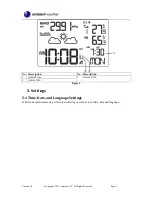
Page 9: ... All Rights Reserved Page 9 No Description No Description 1 Alarm Time 3 Alarm 2 On 2 Alarm 1 On Figure 5 5 Settings 5 1Time Date and Language Settings While in normal time mode perform the following operations to set date time and language ...

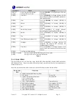
Page 10: ...DE German ES Spanish and IT Italian TIME Time Zone Press CHANNEL to change between auto most of USA and Canada and OFF Arizona and Hawaii TIME Exit Time and Date Settings TIME 2 seconds means press and hold the TIME button for two seconds TIME means press but do not hold the TIME button Figure 6 5 1 1 Hour Offset The clock allows you to set four time zones Pacific PST Mountain MST Central MST and ...

Page 11: ...ARM 2 seconds Enter Alarm Settings Alarm Hour Press CHANNEL to increase MEM to decrease ALARM Alarm Minute Press CHANNEL to increase MEM to decrease ALARM Exit Alarm Settings ALARM 2 seconds means press and hold the ALARM button for two seconds ALARM means press but do not hold the ALARM button Figure 7 5 2 1 Using the Alarm and Snooze Functions 1 Set the alarm time as described in Section 5 2 Whi...

Page 12: ...e Slide the PROJECTION ON OFF switch to OFF position and the projection will be off all of the time unless you press the SNOOZE LIGHT button as described in the previous section Slide the LIGHT ON OFF switch to ON position and the backlight will be on all the time Slide the LIGHT ON OFF switch to OFF position and the backlight will be off all of the time unless you press the SNOOZE LIGHT button as...

Page 13: ...mode or wait 60 seconds to time out Note After calibration the barograph will reset to 0 change flat line across the graph 5 4 3 1 Relative vs Absolute Pressure and Calibration The clock displays two different pressures absolute measured and relative corrected to sea level To compare pressure conditions from one location to another meteorologists correct pressure to sea level conditions Because th...

Page 14: ...me they were reset Command Mode Settings MEM Displays Outdoor Maximum Temperature and the associated date and time Press and hold MEM for two seconds to reset the maximum outdoor temperature to the current value MEM Displays Outdoor Minimum Temperature and the associated date and time Press and hold MEM for two seconds to reset the minimum outdoor temperature to the current value MEM Displays Indo...

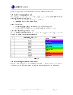
Page 15: ... ON OFF button to constantly loop through all of the 13 colors 5 8 2 Outdoor Temperature Color Place the MANUAL TEMP COLOR slide switch in the temp position The display color will automatically change based on the color chart below Temperature Range F Color 1 0 White 2 0 10 Violet 3 10 20 Dark Blue 4 20 30 Light Blue 5 30 40 Dark Aqua 6 40 50 Light Aqua 7 50 60 Green 8 60 70 Light Green 9 70 80 Ye...

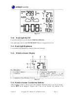
Page 16: ...de the L H switch low high 5 12 Wireless Sensor Display No Description No Description 1 Low Battery Indicator 4 Temperature Channel Number 2 Temperature 5 Channel Number default 1 and Reception Icon on when searching flashes when updates 3 Temperature Units of Measure F or C Figure 13 5 13 Wireless Sensor Low Battery Indictor When the battery is full no battery icon will be displayed When the batt...

Page 17: ...y will show dashes Wait several minutes for resynchronization To reset the console disconnect from AC power and remove the batteries for 10 seconds then reinsert the batteries and reconnect AC power Alternately you can press the RESET button on the back of the console The sensor display will show dashes Wait several minutes for resynchronization 5 16 Adding Multiple Wireless Sensors If you introdu...

Page 18: ... 1100mb 25 C 1hPa 0 01inHg 0 1mmHg 6 2 Power Consumption Display 3 x AAAlkaline batteries recommended Display DC 4 5V 300mA adaptor Wireless Transmitter 2 x AA Alkaline batteries recommended Lithium e2 Energizer for cold weather 7 Troubleshooting Guide If your question is not answered here you can contact us as follows 1 Email Support support ambientweather com 2 Technical Support 480 346 3380 M F...

Page 19: ...closer location Radio Frequency RF Sensors cannot transmit through metal barriers example aluminum siding or multiple thick walls The clock does not respond to commands Press the reset button on the back of the clock with an open ended paper clip or sharp tool The projection is fuzzy Adjust the focus setting The clock is dim when running on batteries only Press the snooze light button or connect t...

Page 20: ...ent has been tested and found to comply with the limits for a Class B digital device pursuant to Part 15 of the FCC Rules These limits are designed to provide reasonable protection against harmful interference in a residential installation This equipment generates uses and can radiate radio frequency energy and if not installed and used in accordance with the instructions may cause harmful interfe...

Page 21: ...er s manual 3 damage resulting from the performance of repairs or alterations by someone other than an authorized Ambient LLC authorized service center 4 units used for other than home use 5 applications and uses that this product was not intended 6 the products inability to receive a signal due to any source of interference or metal obstructions and 7 extreme acts of nature such as lightning stri...

Reviews: