Set the volume control potentiometer to the power off position (rotate to fully counterclowise position
until you feel a click) before you install it on the board.
Since the Mini³ circuit board holes are plated through, with the exception of the SMT opamps (or if
you chose to use the SMT schottky diodes for D2 and D3), you only need to solder the parts from the
bottom of the board. Do not drill or enlarge the holes because that would damage the through-plating.
Make sure the correct part goes into each position on the circuit board. Measure each resistor with
your multimeter to ensure it's the proper value before installing it. Pay attention to the polarity of
electrolytic and tantalum capacitors, diodes, voltage regulators and rail splitter chip. For electrolytic
and tantalum capacitors, the positive lead should be the longer one.
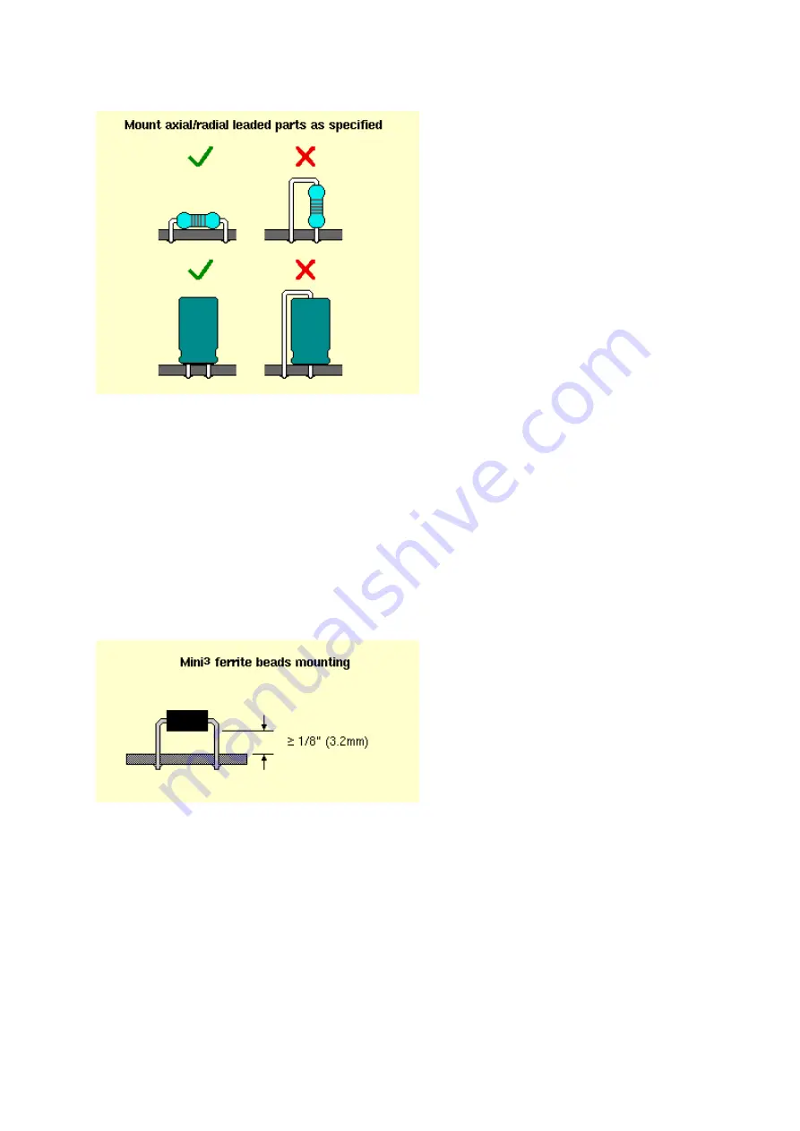
The ferrite beads should be mounted elevated from the board surface, allowing at least 1/8" (3.2mm)
clearance, as shown in the following picture:
The U2 voltage regulator should have its pins bent 90° downward for insertion into the board. You
must check that the mounting hole is aligned properly while the pins are bent to fit their pads. Apply a
small amount of heatsink compound to the bottom of the regulator to help it transfer heat to the board.
No isolation pad or TO-220 mounting kit is needed. The imperial #4-40 or metric M3 mounting screw
should have a low-profile pan head (so as not to touch the case when the board is installed), or you
could use a nylon screw. The screw should be inserted from the bottom up. Secure the regulator
using a hex nut from above (see photo above) before soldering the regulator's pins.
When soldering the DC power jack and 3.5mm stereo mini jacks, you should heat the solder tabs and
pads sufficiently to allow solder to fill the entire hole. Remove heat immediately and cool the joint by
blowing air at it as soon as you achieve a good fill. This assures that the jacks will be mechanically-
secure.


