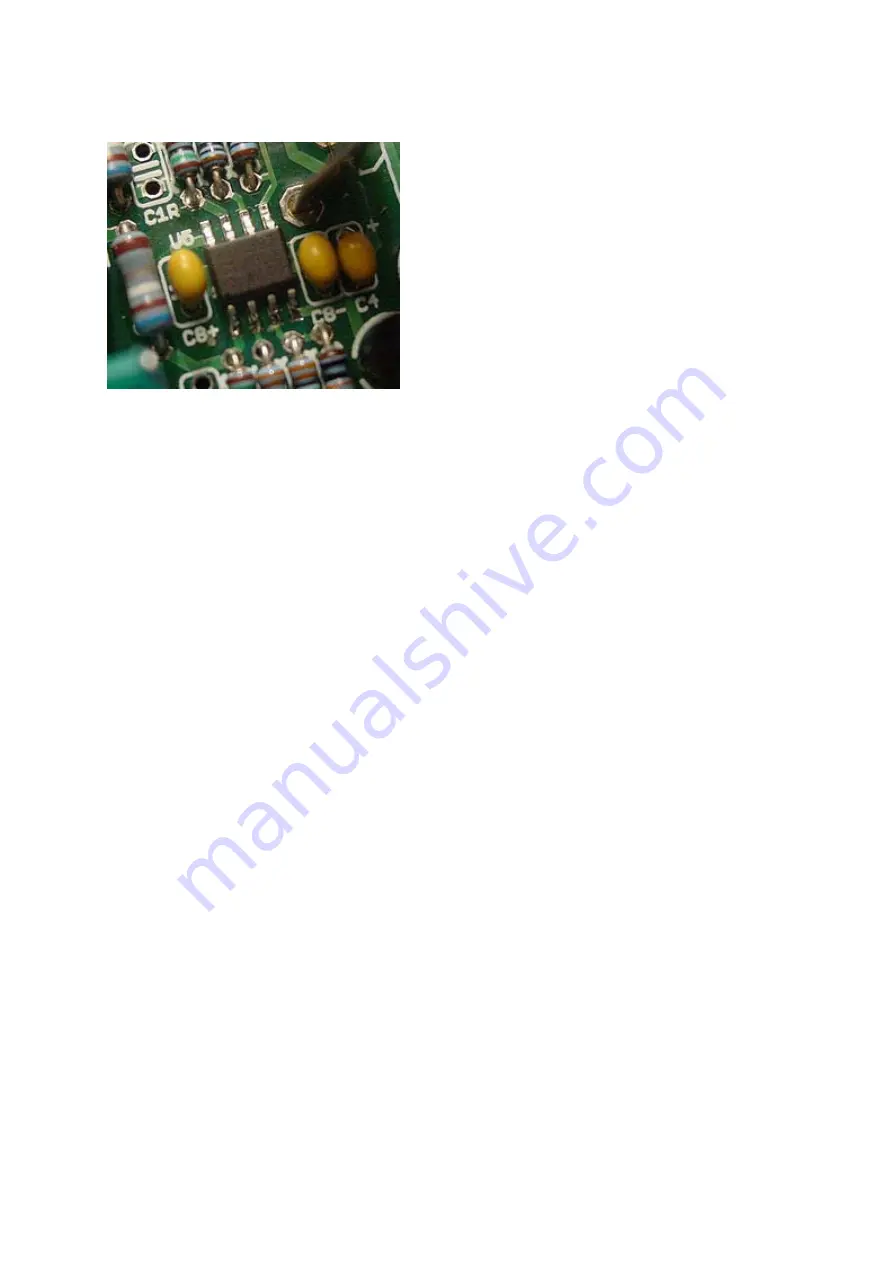
When done, your solder joints should look something like this:
Use your multimeter and check the resistance between each pin of the opamp and the pad to make
sure you don't have a cold solder joint (i.e., your meter should read close to zero ohms). Also check
continuity between adjacent pins for solder bridges (meter should read infinity).
Repeat the above procedure for the U4 opamp. When you are done with the opamps, use a Q-tip and
isopropyl alcohol, or specialized electronics flux remover to clean off the flux.
Now mount and solder the rest of the parts, starting with the lowest profile parts and work up, in the
following order (see details below):
•
Resistors
•
Diodes
•
Multilayer ceramic capacitors
•
Voltage Regulators U1, U2
•
Rail-splitter chip U3
•
Ferrite beads L1L, L1R, L1G
•
Tantalum capacitor C2
•
Electrolytic capacitor C5+, C5-
•
Volume control potentiometer
•
DC power jack J1
•
3.5mm stereo mini phone jacks J2, J3
•
Electrolytic capacitor C3a, C3b
•
LEDs
•
Battery contacts B+, B-


