background image


Layout and function 


XTender  BAG0158.2  03.18 

45 


5.3.3 

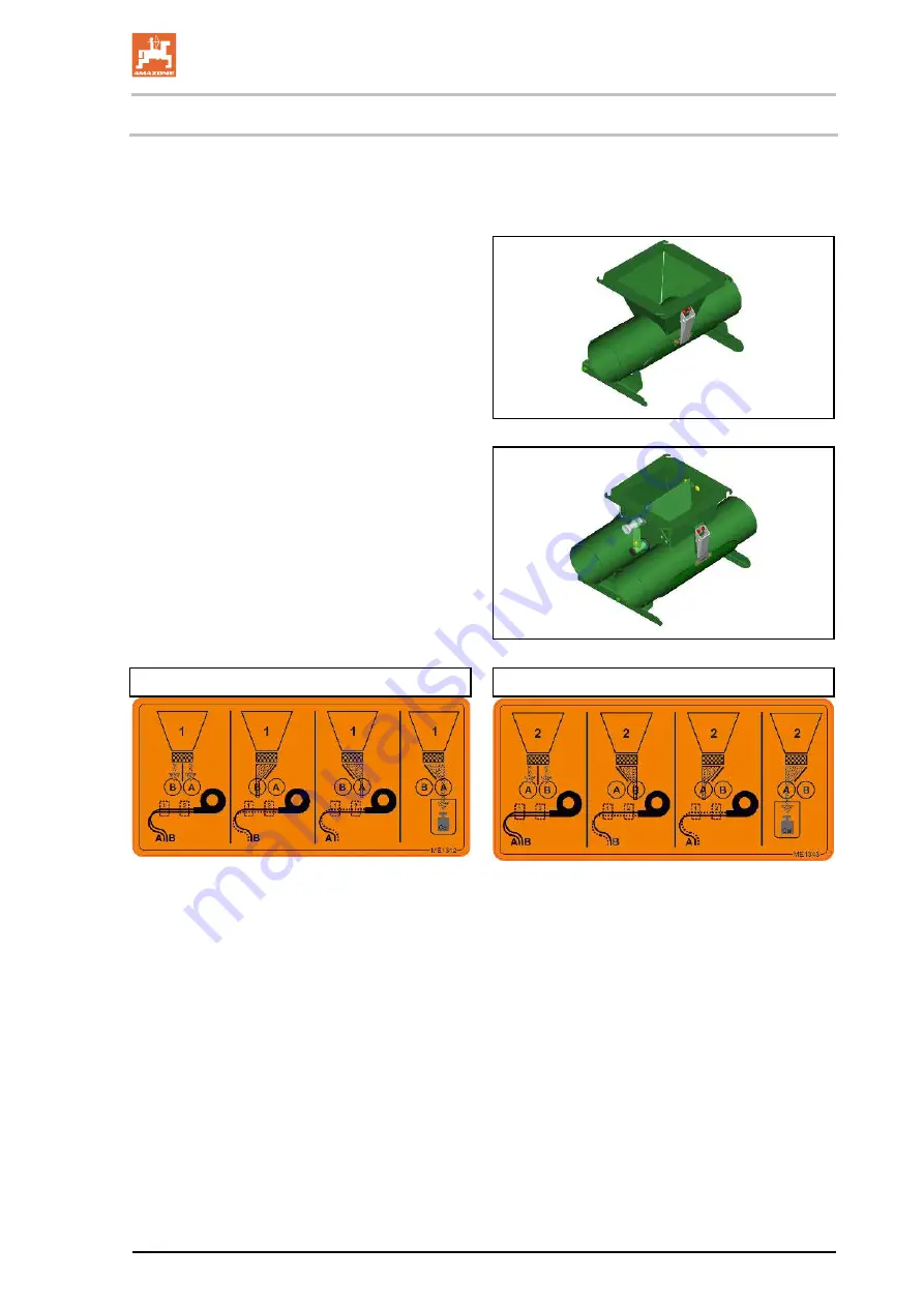
Sluices 

The sluices are equipped with a calibration flap 
and a holder for the calibration sack. Mechanical 
one-sided switching is possible with the double 
sluice. 


Single sluice on single conveyor section  


Double sluice with setting flap and setting lever 
on double conveyor section 


Double sluice: 


Hopper 1 


Hopper 2 


Depending on the position of the setting lever, 
the respective double sluice coveys from hopper 
1 and 2 in conveyor section A or / and B. 

Select conveyor section A for calibration. 


Summary of Contents for XTender 2200

Page 1: ...rating manual az XTender 2200 XTender 4200 Rear mounted hopper MG5828 BAG0158 2 03 18 Printed in Germany Please read this operating manual before initial operation Keep it in a safe place for future use en ...

Page 2: ...person concerned would not only harm himself but also make the mistake of blaming the machine for the reason of a possible failure instead of himself In order to ensure a good success one should go into the mind of a thing or make himself familiar with every part of the machine and to get acquainted with its handling Only this way you would be satisfied both with the machine as also with yourself ...

Page 3: ... WERKE H DREYER GmbH Co KG Postfach 51 D 49202 Tel E mail Hasbergen Germany 49 0 5405 501 0 amazone amazone de Spare part orders Spare parts lists are freely accessible in the spare parts portal at www amazone de Please send orders to your AMAZONE dealer Formalities of the operating manual Document number MG5828 Compilation date 04 16 Copyright AMAZONEN WERKE H DREYER GmbH Co KG 2018 All rights re...

Page 4: ...icularly the safety information Only after careful reading will you be able to benefit from the full scope of your newly purchased implement Please ensure that all the implement operators have read this operating manual before they put the implement into operation Should you have any questions or problems please consult this operating manual or contact your local service partner Regular maintenanc...

Page 5: ...15 Safety conscious working 20 2 16 Safety information for users 21 2 16 1 General safety instructions and accident prevention instructions 21 2 16 2 Hydraulic system 25 2 16 3 Electrical system 26 2 16 4 Operation of the seed drill 26 2 16 5 Cleaning maintenance and repair 27 3 Loading and unloading 28 4 Product description 29 4 1 Overview of assembly groups 29 4 2 Thread pack with machine docume...

Page 6: ...ront axle load of the tractor TV tat 65 6 1 1 4 Calculation of the actual total weight of the combined tractor and implement 65 6 1 1 5 Calculation of the actual rear axle load of the tractor TH tat 65 6 1 1 6 Tractor tyre load capacity 65 6 1 1 7 Table 66 6 2 Securing the tractor implement against unintentional start up and rolling 67 7 Coupling and uncoupling the implement 68 7 1 Coupling the im...

Page 7: ...ributor head specialist workshop 96 12 1 2 Seeding shaft bearing 96 12 2 Maintenance schedule overview 97 12 3 Checking the frame 98 12 4 Brake system 99 12 4 1 Cleaning the line filter 99 12 4 2 Inspection instructions for pneumatic brake 100 12 5 Hydraulic system 101 12 5 1 Labelling of hydraulic hose lines 102 12 5 2 Maintenance intervals 102 12 5 3 Inspection criteria for hydraulic hose lines ...

Page 8: ...ating manual All the directions specified in the operating manual are always seen in the direction of travel 1 3 Diagrams Instructions and responses Activities to be carried out by the user are given as numbered instructions Always keep to the order of the instructions The reaction to the handling instructions is given by an arrow Example 1 Instruction 1 Reaction of the implement to handling instr...

Page 9: ...on the implement in a legible state to replace damaged warning symbols Obligations of the user Before starting work anyone charged with working with on the implement is obliged to comply with the basic workplace safety instructions and accident prevention regulations to read and understand the General safety information section of this operating manual to read the section Warning symbols and other...

Page 10: ... shall be available to the operator at the latest on conclusion of the contract Guarantee and liability claims for damage to people or property will be excluded if they can be traced back to one or more of the following causes Improper use of the implement Improper installation commissioning operation and maintenance of the implement Operation of the implement with defective safety equipment or im...

Page 11: ...death or serious physical injury WARNING Indicates a medium risk which could result in death or serious physical injury if not avoided If the instructions are not followed then this may result in death or serious physical injury CAUTION Indicates a low risk which could cause minor or medium level physical injury or damage to property if not avoided IMPORTANT Indicates an obligation to special beha...

Page 12: ...personnel Check all the available safety equipment regularly 2 4 Safety and protective equipment Before starting up the implement each time all the safety and protection equipment must be properly attached and fully functional Check all safety and protection equipment regularly Faulty safety equipment Faulty or disassembled safety and protection equipment can lead to dangerous situations 2 5 Infor...

Page 13: ...nstructed persons are those who have been instructed in their assigned tasks and in the possible risks in the case of improper behaviour have been trained if necessary and have been informed about the necessary protective equipment and measures 3 People with specialist technical training shall be considered as a specialist Due to their specialist training and their knowledge of the appropriate reg...

Page 14: ...n the implement Use appropriate measures to inform the operating personnel You can find detailed information in the relevant sections of this operating manual 2 9 Maintenance and repair work fault elimination Carry out prescribed setting maintenance and inspection work in good time Secure all media such as compressed air and the hydraulic system against unintentional start up Carefully fix and sec...

Page 15: ...trictly forbidden to drill holes in the frame or on the running gear increase the size of existing holes on the frame or the running gear weld support parts 2 10 1 Spare and wear parts and aids Immediately replace any implement parts which are not in a perfect state Use only genuine AMAZONE spare and wear parts or the parts cleared by AMAZONEN WERKE so that the operating permit retains its validit...

Page 16: ...ing symbol consists of two fields Field 1 is a symbol describing the danger surrounded by triangular safety symbol Field 2 is a symbol showing how to avoid the danger Warning symbols explanation The column Order number and explanation provides an explanation of the neighbouring warning symbol The description of the warning symbols is always the same and specifies in the following order 1 A descrip...

Page 17: ...General safety instructions XTender BAG0158 2 03 18 17 2 13 1 Positions of warning symbols and other labels The following diagrams show the arrangement of the warning symbols on the implement ...

Page 18: ...ement MD 095 Before commissioning the implement read and observe the operating manual and the safety instructions carefully MD 096 Danger from escaping high pressure hydraulic fluid due to leaking hydraulic hose lines This danger may cause serious injuries perhaps even resulting in death if escaping high pressure hydraulic fluid passes through the skin and into the body Never attempt to plug leaks...

Page 19: ...if you are in the lifting area between the tractor and implement MD 100 This symbol indicates attachment points for lifting gear for loading the implement MD 102 Danger from intervention in the implement e g installation adjusting troubleshooting cleaning maintaining and repairing due to the tractor and the implement being started unintentionally and rolling These dangers can cause extremely serio...

Page 20: ...risks Risk to people from working in an unsafe working environment Failure of important implement functions Failure of prescribed methods of maintenance and repair Risk to people through mechanical and chemical influences Risk to the environment through leakage of hydraulic fluid 2 15 Safety conscious working Besides the safety information in this operating manual the generally applicable national...

Page 21: ...he implement check the immediate area of the implement children Ensure that you can see clearly It is forbidden to ride on the machine or use it as a means of transport Drive in such a way that you always have full control over the tractor with the attached implement In so doing take your personal abilities into account as well as the road traffic visibility and weather conditions the driving char...

Page 22: ...e the support equipment if available to the appropriate position stability When actuating the support equipment there is a danger of injury from contusion and cutting points Be particularly careful when coupling the implement to the tractor or uncoupling it from the tractor There are nip and shear points in the area of the coupling point between the tractor and the implement It is forbidden to sta...

Page 23: ...uated by external force if personal are maintaining an adequate safety distance to the implement Secure the tractor against unintentional start up and rolling before you leave the tractor For this ο Lower the implement onto the ground ο Apply the tractor parking brake ο Switch off the tractor engine ο Remove the ignition key Implement transportation When using public roads national road traffic re...

Page 24: ...road transport move all the swivel implement parts to the transport position Before road transport secure all the swivel implement parts in the transport position against risky position changes Use the transport locks intended for this Before road transport secure the operating lever of the three point hydraulic system against unintentional raising or lowering of the coupled implement Before road ...

Page 25: ... brake ο Take out the ignition key Have the hydraulic hose lines checked for proper functioning by a specialist at least once a year Replace the hydraulic hose lines if they are damaged or worn Use only genuine AMAZONE hydraulic hose lines The hydraulic hose lines should not be used for longer than six years including any storage time of maximum two years Even with proper storage and approved use ...

Page 26: ...luenced by electromagnetic interference from other units Such interference can pose risks to people if the following safety information is not followed ο In the case of retrofitting electrical units and or components on the implement with a connection to the on board power supply the operator is responsible for checking whether the installation might cause faults on the vehicle electronics or othe...

Page 27: ...cessary Secure the raised implement or raised implement parts against unintentional lowering before performing any cleaning maintenance or repair work on the implement When replacing work tools with blades use suitable tools and gloves Dispose of oils greases and filters in the appropriate way Disconnect the cable to the tractor generator and battery before carrying out electrical welding work on ...

Page 28: ...e sure to use the marked lashing points to attach the load bearing equipment when you load and unload the implement with lifting gear Use load bearing equipment with a respective load capacity of at least 400 kg Never remain in or enter the area below the raised implement Loading using a lifting crane This symbol indicates attachment points for lifting gear for loading the implement ...

Page 29: ...ressure lids 3 Metering unit 4 Connections for the supply line from the Cenius 5 Coupling points for mounting the Cenius 6 Connection for the seed tube hoses 7 Folding loading board in different versions 8 Rear camera optional 9 Rear lighting 10 Work lights optional 11 Storage compartment 12 TwinTerminal optional ...

Page 30: ...an 2 Parking device rolls with brakes 3 Parking device runners optional 4 3 point hitch 5 Front lighting Delivery section Here a double delivery section 1 Implement connection 2 Supply line 3 Segment distributor head 4 Feed hose 5 Baffle plate for catch crops ...

Page 31: ...Product description XTender BAG0158 2 03 18 31 4 2 Thread pack with machine documentation The thread pack with the implement documentation is behind the left mud flap ...

Page 32: ...Product description 32 XTender BAG0158 2 03 18 4 3 Safety and protective equipment 1 Blower fan guard Railing on the loading board XTender 4200 Guard screen in the hopper ...

Page 33: ...etween the tractor and the implement Hydraulic hose lines depending on the equipment Cable with connection for lighting ISOBUS connection cable Pneumatic brake system ο Brake line with coupling head yellow ο Supply line with coupling head red Yellow Blue Green Beige ...

Page 34: ...2 Rear warning signs Front lighting system 1 Limiting lights and turn indicators 2 Front warning signs Connect the lighting system to the 7 pin tractor socket via the pin Connect the lighting system to the 7 pin tractor socket via the pin Connect the lighting system for the soil tillage implement to the 7 pin socket of the XTender using the plug ...

Page 35: ...nts that fulfil the requirements for the coupling device and drawbar load Slopes can be travelled ο Across the slope Direction of travel to the left 15 Direction of travel to the right 15 ο Up and down the slope Up the slope 15 Down the slope 15 Intended use also covers Compliance with all the instructions in this operating manual Execution of inspection and maintenance work Exclusive use of genui...

Page 36: ...g as the tractor engine is running with a connected universal joint shaft hydraulic system as long as the tractor and implement are not protected against unintentional start up and running The operating person may only move the implement or switch or drive the tools from the transport position to the working position or vice versa when there is no one in the implement danger area Danger points exi...

Page 37: ...otal weight 4250 7200 kg Payload 3060 kg 5900 kg Permissible drawbar load for the hitch 3000 kg d Distance between lower link connection point and the centre of gravity 900 mm Maximum trailer load 15000 kg GH Total weight of rear mounted implement plus drawbar load with full use of the payload Cenius 4003 5003 2TX 5180 kg 8130 kg Cenius 6003 7003 2TX 5559 kg 8509 kg Certos 4000 5000 2TX 6880 kg 98...

Page 38: ...ar with blower fan drive via tractor control unit Implement hydraulic fluid HLP68 DIN 51524 The implement hydraulic fluid is suitable for the combined hydraulic fluid circuits of all standard tractor brands Control units see Seite 40 Three point hitch The lower links of the tractor must have lower link hooks The top links of the tractor must have top link hooks 4 11 Noise production data The workp...

Page 39: ...an be spread during soil tillage To achieve this the two part hopper has a metering unit for each partition which meters the spreading material through the sluice into the conveyor section The compressed air from the blower fan carries the spreading material to the distributor From there the spreading material is distributed across the working width The XTender can be equipped with one conveyor se...

Page 40: ...tor control unit must be used in different types of activation depending on the hydraulic function Latched for a permanent oil circulation Tentative activate until the action is executed Float position free oil flow in the control unit Marking Function Tractor control unit Yellow Running gear drawbar Move into working position Double acting Move into headlands position into transport position Blue...

Page 41: ...If you are injured by hydraulic fluid contact a doctor immediately Maximum permissible pressure in the oil return 5 bar Therefore do not connect the oil return to the tractor control unit but rather to a pressure free oil return with a large plug coupling WARNING Only use DN16 lines for the oil return and select short return paths Only apply pressure to the hydraulic system when the free return li...

Page 42: ...l oils Observe the maximum approved hydraulic fluid pressure of 210 bar Only couple clean hydraulic connectors Push the hydraulic connector s into the hydraulic sleeves until you feel them lock Check the coupling points of the hydraulic hose lines for a correct tight seat 1 Put the tractor control unit into float position neutral 2 Clean the hydraulic connectors of the hydraulic hose lines before ...

Page 43: ...of the implement is designed such that it meets the requirements and dimensions of a Category 3 or 4N three point hitch 1 Lower coupling points 2 Upper coupling point Pins for mounting on tractors with Category 3 or 4N coupling points with linch pin for securing the lower link and top link ...

Page 44: ... conveyor section Different products e g fertiliser seed 1 Hopper 1 with metering unit 1 2 Hopper 2 with metering unit 2 3 Single sluice 4 Double sluice for delivery section A and B 5 Blower fan Adjustable air distributor for the double delivery section When spreading fine seeds and fertiliser use the maximum air current for transporting the fertiliser ...

Page 45: ...switching is possible with the double sluice Single sluice on single conveyor section Double sluice with setting flap and setting lever on double conveyor section Double sluice Hopper 1 Hopper 2 Depending on the position of the setting lever the respective double sluice coveys from hopper 1 and 2 in conveyor section A or and B Select conveyor section A for calibration ...

Page 46: ...with the same or with different products 2 1 The hopper covers seal the hopper pressure tight Viewing window at the front and rear show the fill level in the hopper The charging sieves serve as protection against accidental contact with the metering unit as protection against foreign particles and fertiliser clumps when filling There is a fill level sensor in the hopper with height adjustable atta...

Page 47: ... 03 18 47 5 5 Loading board XTender 4200 Loading board and ascent can be folded Push the ascent under the maintenance platform into transport position and secure with a linch pin 5 6 XTender 2200 loading platform Foldable loading platform ...

Page 48: ... speed of the metering roller is determined when calibrating the spread rate determines the spread rate The higher the speed of the electric motor the greater the spread rate automatically adjusts to changing working speeds can be increased during operation by the press of a button on the control terminal when the soil changes from normal to heavy The working speed is determined e g by pulses from...

Page 49: ...hamber of the two chamber system The metering units are numbered Metering unit no 1 is connected to the front chamber When calibrating the spread rate the metered material falls into the collection bag through an opening 1 The calibration procedure is performed consecutively on both metering units A flap 1 closes the opening ...

Page 50: ...ieved during the second calibration procedure Otherwise repeat the calibration procedure until the required spread rate is achieved Always perform a calibration procedure during the initial operation when changing the sort if the seed type is identical but the grain size grain shape specific weight and dressing are different after replacing the metering roller if the hopper takes more less time th...

Page 51: ...ional The TwinTerminal is located in the metering area and saves the tractor driver the walk over to the tractor cab e g when starting the calibration procedure or entering the collected calibrated quantity Also during residual emptying of the hopper the metering roller motor which drives the metering roller in the metering unit is switched on and off using the TwinTerminal Like with the calibrati...

Page 52: ...rning and actuating the control unit yellow the implement moves into working position Seed is metered into the delivery line The start up ramp compensates for system related seed rate reductions during the acceleration phase of the implement The factory settings can be adapted For this purpose the intended working speed set in the Calibration menu is used The starting speed and the time until the ...

Page 53: ...at is not too large but that is sufficient to spread the required quantity kg ha During the calibration procedure check whether the selected metering roller achieves the spread rate For sowing particularly large seeds e g large beans the chambers 1 of the metering roller can be enlarged by repositioning the wheels and the plates The volume of some metering rollers can be modified by repositioning ...

Page 54: ...5 20 40 cm 3 120 210 350 cm 3 600 660 Metering rollers with different capacities are available Select the metering roller required depending on the seed or the fertiliser and the spread rate according to the following tables If the seed is not listed select the metering roller of a seed that has a similar grain size ...

Page 55: ...al displays the current blower fan speed and issues an alarm if there is a deviation from the nominal speed 5 8 1 Segment distributor head The metered material is evenly distributed over all of the segments in the segment distributor head and is carried to the spreading elements through the connected seed line tubes Individual segments of the distributor head can be replaced by tramline segments 1...

Page 56: ...connection between the distributor head and the spreading elements Each seed tube hose can be equipped with a sensor 1 that detects the seed flow A warning message is issued when the seed flow in a monitored seed line hose is interrupted or large deviations occur in the flow rate between the monitored seed line hoses ...

Page 57: ... Under root fertilising 2 50 under root fertilising 50 subsoil fertilising 3 Subsoil fertilising Fertilisers Working width m Number of outlets on the distributor head tine Line distance mm 4 26 13 307 5 17 17 294 6 21 21 286 7 25 25 280 Seed spreading Spreading of seed via baffle plates Catch crop Working width m Number of outlets on the distributor head Line distance mm 4 17 235 5 17 294 6 21 286...

Page 58: ...on sensor on the soil tillage implement To control the metering unit the soil tillage implement must be equipped with a working position sensor 5 12 Radar The radar is used to detect the working speed The working speed data is used to determine the worked area hectare counter the required speed for the speed of the metering roller s 5 13 Work floodlights The LED work floodlights optional at the re...

Page 59: ...ation makes the area hidden by the hopper visible The large monitor in the tractor cab shows the work of the implement tools and the worked area The monitor is characterised by the clear glare free representation of multiple camera images simultaneously The camera system can be quickly mounted and dismounted with simple plug connections 5 15 Service box Transport of accessories like e g a calibrat...

Page 60: ... When setting down the rear hopper the hopper may only contain a small residual quantity Put the transport and parking device in out of operation 1 Raise the machine and secure to prevent unintentional lowering 2 Secure the tractor against unintentional rolling 3 Fasten the rear rollers individually onto the frame from the side from the bottom 4 Swivel the front rollers individually towards the re...

Page 61: ...h a tractor which is suitable for the task The tractor and implement must meet the national road traffic regulations The operator and the user shall be responsible for compliance with the statutory road traffic regulations WARNING Risk of contusions cutting catching drawing in and knocks in the area of hydraulically or electrically actuated components Do not block the operator controls on the trac...

Page 62: ... achieves the required braking delay with the implement connected Requirements for the suitability of a tractor are in particular The permissible total weight The permissible axle loads The permissible drawbar load at the tractor coupling point The load capacity of the installed tyres The permissible trailer load must be sufficient You can find this data on the rating plate or in the vehicle docum...

Page 63: ...drawbar load of the hitched implement This notice applies only to Germany If having tried all possible alternatives it is not possible to comply with the axle loads and or the permissible total weight then a survey by an officially recognised motor traffic expert can with the approval of the tractor manufacturer be used as a basis for the responsible authority to issue an exceptional approval acco...

Page 64: ...nt implement mounting or front weight or measurement a1 m Distance from the centre of the front axle to the centre of the lower link connection See tractor operating manual or measurement a2 m Distance between the centre of the lower link connection point and the centre of gravity of the front mounted implement or front ballast centre of gravity distance See technical data of front implement mount...

Page 65: ...ractor operating manual in the table section 6 1 1 7 6 1 1 4 Calculation of the actual total weight of the combined tractor and implement H L V tat G T G G Enter the numeric value for the calculated actual total weight and the approved total tractor weight specified in the tractor operating manual in the table section 6 1 1 7 6 1 1 5 Calculation of the actual rear axle load of the tractor TH tat t...

Page 66: ...nd insufficient tractor steering and brake power It is forbidden to couple the implement to the tractor used as the basis for calculation if one of the actual calculated values is greater than the approved value there is no front weight if required attached to the tractor for the minimum front ballast GV min Ballast your tractor with weights at the front or rear if the tractor axle load is exceede...

Page 67: ...implement such as installation adjustment troubleshooting cleaning maintenance and repairs while the implement is being driven as long as the tractor engine is running with the PTO shaft hydraulic system connected if the ignition key is inserted in the tractor and the tractor engine can be started unintentionally with the tractor PTO shaft hydraulic system connected if the tractor and implement ha...

Page 68: ...entional starting and rolling before entering the danger area between the tractor and implement to couple or uncouple the universal joint shaft and supply lines WARNING Risk of crushing and contusions between the rear of the tractor and the implement when coupling and uncoupling the implement It is forbidden to actuate the three point hydraulic system of the tractor as long as persons are standing...

Page 69: ...re the same Only use the upper and lower link pins provided original pins for coupling the implement Check the upper and lower link pins for visible defects whenever the implement is coupled Replace the upper and lower link pins if there are clear signs of wear Use locking pins to secure the upper and lower link pins against accidental loosening Visually check that the upper and lower link hooks a...

Page 70: ...tractor up to the machine in such a way that a gap approx 25 cm remains between tractor and machine 6 2 Secure the tractor against unintentional starting and rolling away 6 3 Check that the tractor s PTO shaft is switched off 6 4 Connect the supply lines for more information see section Connecting hydraulic hose lines starting at page 40 6 5 Connect the light system 6 6 Couple the on board compute...

Page 71: ...y hopper on a horizontal surface with solid ground 2 Always inspect the implement for obvious signs of damage during uncoupling Observe here the chapter Obligations of the user page 9 3 Uncouple the machine from the tractor as follows 3 1 Relieve the top links 3 2 Unlock and uncouple the top link hooks from the tractor seat 3 3 Relieve the lower links 3 4 Unlock and uncouple the lower link hooks f...

Page 72: ... and directs the tractor driver with the coupled XTender towards the towing device of the soil tillage implement The guide may not stand between the implements Supply line interface Connect the supply lines for the soil tillage implement onto the XTender Hydraulic hoses Brake Working position sensor Lighting Pay close attention to the correct connection of the hydraulic hoses and the working posit...

Page 73: ...wering of raised unsecured implement parts unintentional start up and rolling of the tractor implement combination Secure the tractor and the implement against unintentional start up and rolling before working on the implement CAUTION Switching off the control terminal before road transport before adjustment maintenance and repair work Risk of accident due to unintended movements of the metering u...

Page 74: ... a similar grain sizeen 8 1 1 Table metering rollers Seeds Metering rollers cm 7 5 20 40 120 350 600 660 Beans X X Buckwheat X Spelt X Peas X Flax dressed X X X Barley X X X Grass seed Oats X X X Millet X Caraway X Lupins X Alfalfa X X X Maize X Poppy X Oil linen moist dressing X X Fodder radish X X X Phacelia X X X Rapeseed X X X Rye X X X Red clover X X X Mustard X X X Soy X X Sunflowers X Turni...

Page 75: ...ulses The metering roller can be replaced more easily if the hopper is empty 1 Close the opening between the hopper and the metering unit only necessary when the hopper is full 1 1 Remove the key 1 from the holder 1 2 Loosen two nuts 1 but do not remove 1 3 Swivel the bolts 1 1 4 Push the shutter 2 into the metering unit up to the stop 1 5 Push the collection bag 3 under the metering unit and open...

Page 76: ...t remove 3 Turn the bearing cover and pull it off The bearing cover is equipped with an O ring 1 Replace the O ring if it is damaged 4 Remove the metering roller Install the metering roller in the reverse sequence Secure the shutter in the parking position Close the flap ...

Page 77: ...product in the product menu Pre set half of the calibrated quantity for each metering unit e g 50 kg ha for metering unit 1 and 50 kg ha for metering unit 2 100 kg ha total quantity Perform calibration for the product on each metering unit consecutively Double delivery section Two products in the product menu Calibration for each product must be performed successively Calibrate the spread rate usi...

Page 78: ...metering unit 4 Open the sluice flap double sluice only in conveyor section 2 5 Repeat the calibration procedure according to the software operating manual until the desired spread rate is achieved 6 Remove the collection bag 7 Close the sealing flap under the metering unit ...

Page 79: ...hed once the hydraulic fluid has heated up to operating temperature 1 Pressure control valve for the blower fan 8 4 1 Setting the blower fan speed via the flow control valve of the tractor 1 Perform the basic setting of the pressure relief valve according to section 8 4 3 1 2 Read the required blower fan speed from the speed table see section 5 7 3 Set the blower fan speed via the flow control val...

Page 80: ...ontrol valve is connected to the tractor PTO shaft 1 Loosen the lock nut 2 Use the hexagon socket wrench 1 to set the nominal blower fan speed on the pressure relief valve Do not exceed the maximum blower fan speed of 4000 rpm Blower fan speed Turning to the right increases the nominal blower fan speed Turning to the left reduces the nominal blower fan speed 3 Tighten the lock nut 8 4 4 Setting th...

Page 81: ...lace the Y piece with hose by a reduction with hose 2 Remove the blind cap from the frame and install it on the open hose connection 3 Insert unused hose in parking position on the blind cap 4 Fold over the flap for both double sluices so that hopper 1 and hopper 2 convey into the same active conveyor section ...

Page 82: ...s cutting catching drawing in and knocks when making interventions in the implement through unintentional implement movements On folding implements check that the transport locks are locked correctly Secure the implement against unintentional movements before starting transportation WARNING Risk of crushing cutting being caught and or drawn in or impact from tipping and insufficient stability Driv...

Page 83: ...efore approaching the implement WARNING Risk of stabbing other road users through machine parts extending out into the road area Cover any protruding parts on machines You must make protruding parts clearly visible if you can not cover them easily Moving the implement in the transport position 1 Switch off the blower fan 2 When transporting the implement on public roads switch off the work floodli...

Page 84: ...y that you always have full control over the tractor with the mounted or trailed implement In so doing take your personal abilities into account as well as the road traffic visibility and weather conditions the driving characteristics of the tractor and the connected or coupled implement WARNING Danger of crushing shearing cutting being caught or drawn in winding and knocks through unintentional l...

Page 85: ...tractor implement against accidental start up and rolling DANGER Dressing dust is toxic and must not be inhaled or come into contact with the body Dressing dust may escape when filling the implement Wear a face mask and protective goggles and gloves If the control device triggers an alarm when the theoretically calculated residual quantity is reached in the hopper enter the filling quantity kg in ...

Page 86: ... board and fold it down 2 Release the locking mechanism for the railing fold up the railing and lock it 3 Pull out the linch pin on the ladder pull it out and fold down Folding the loading board into transport position 1 Lift the ladder push it into the holder and lock with a spring cotter pin 2 Release the locking mechanism on the railing fold it down and lock it 3 Fold up the loading board and l...

Page 87: ...ser Refer to the Implement control operating manual Check that all components are in working position Check the seed and fertiliser lines Dressed seed is very toxic for birds The seed must be fully incorporated or covered with soil Avoid seed trickling out when lifting the coulters Immediately pick up spilled seed From time to time check the distributor heads from the tractor seat for impurities D...

Page 88: ...earance of 20 30 cm see figure 1 3 Unfold the implement sections of the trailed soil tillage implement and move into working position see operating manual for the respective implement 1 4 Teach in the limit values for the working position sensor when changing the working depth on the soil tillage implement 2 Check all implement settings 3 Run the blower fan up to nominal speed 4 Start driving and ...

Page 89: ... contact with the body When emptying the hopper and metering housing or when removing dressing dust e g with compressed air wear a protective suit face mask safety goggles and gloves Empty and carefully clean the fertiliser hopper daily after work Remaining fertiliser can damage the metering unit Seed residues left in the metering unit can swell or germinate if the metering unit is not completely ...

Page 90: ...metering roller motor is generally switched on and off on the control terminal in the tractor cab As an option the Twin Terminal can be connected to the control terminal in the tractor cab and be attached directly beside the metering unit to make entries using the keyboard 10 5 2 Emptying the metering unit The metering unit can be emptied as described in section 10 3 1 page oben It is recommended ...

Page 91: ...o a deviation between the preset and actual seeding rates For recording the worked area and the required seed spread rate pulses of the radar are required over a calibration distance of 100 m Field surfaces change during work e g when changing from dry light soil to wet heavy soil This can also alter the calibration value Pulse 100 m If there are differences between the preset and actual seeding r...

Page 92: ...unintentional rolling away before you perform any cleaning servicing or maintenance work on the machine See page 67 WARNING Risk of crushing shearing cutting being caught and or drawn in or impact through unprotected danger points Mount protective equipment which you removed when cleaning maintaining and repairing the implement Replace defective protective equipment with new equipment DANGER When ...

Page 93: ...nd maintenance work Observe legal requirements when disposing of lubricants e g oils and grease Also affected by these legal requirements are parts that come into contact with these lubricants Do not exceed a greasing pressure of 400 bar when greasing with high pressure grease guns The following are prohibited ο drilling the running gear ο drilling through pre existing holes on the transport frame...

Page 94: ...ched faults may occur in the seed delivery and distribution Clean the blower fan of any deposits Deposits lead to imbalance and damage to the bearing Cleaning with a high pressure cleaner steam jet Always observe the following points when using a pressure washer steam jet for cleaning ο Do not clean any electrical components ο Do not clean any chrome plated components ο Never aim the cleaning jet ...

Page 95: ...he pictogram serves as a reminder never to aim the cleaning jet of the high pressure cleaner steam cleaner directly on electrical components lubrication points and bearings the rating plate warning symbols stickers and design foils The components can be damaged ...

Page 96: ... ignition key Before approaching clean the path to the distributor head and the area of the distributor head danger of slippage There is the risk of an accident on the path to the distributor head and in the area of the distributor head 1 Open the inspection cover 1 to remove light soiling 2 Remove the cover plate for intensive cleaning 2 3 Remove impurities with a broom or with compressed air Wip...

Page 97: ...rn or damaged hose and tubes immediately 4 Fix leaky connections immediately After the first working run Component Servicing work See page Specialist workshop Hydraulic system Check for defects Check leak tightness 97 Daily Component Servicing work See page Specialist workshop Metering unit empty 90 Blower fan Clean the blower fan risk of unbalancing Spreading Check for and remove any impurities ο...

Page 98: ...ecialist workshop Frame Check for damage and deformation Check the fastening bolts for tightness 98 Brake system Check according to the inspection instructions 100 X Clean the line filters 99 12 3 Checking the frame Check the frame for the following points Damage deformation Tightness of the fastening bolts ...

Page 99: ...mmering and remove the bolts 1 2 Unscrew the bolts 2 by a few turns 3 Lift the plate 3 over the rubber seal 4 and turn to the side The unit is under spring tension 4 Remove the rubber seal 5 Clean and grease the sealing surfaces O ring and filter Replace the rubber seal if necessary Correctly position the O ring on the plastic ring 6 Reassemble in the reverse sequence Bolt tightening torque 1 2 5 ...

Page 100: ...al any leaking areas or replace leaking valves 2 Checking the pressure in the air reservoir 1 Connect a pressure gauge to the test connection on the air reservoir Target value 6 0 to 8 1 0 2 bar 3 Checking the brake cylinder pressure 1 Connect a pressure gauge to the test connection on the brake cylinder Target value with brake not applied 0 0 bar 4 Visual inspection of brake cylinder 1 Check the ...

Page 101: ...he trailer Ensure that the hydraulic hose lines are connected correctly Regularly check all the hydraulic hose lines and couplings for damage and impurities Have the hydraulic hose lines checked at least once a year by a specialist for proper functioning Replace the hydraulic hose lines if they are damaged or worn Only use genuine AMAZONE hydraulic hose lines The hydraulic hose lines should not be...

Page 102: ...ace any worn or damaged hydraulic hose lines immediately 12 5 3 Inspection criteria for hydraulic hose lines For your own safety comply with the following inspection criteria Replace hydraulic hose lines on determining any of the following during the inspection Damage to the outer layer up to the ply e g scouring points cuts cracks Brittleness of the outer layer crack formation of the hose materia...

Page 103: ...apart from the hose s own weight ο There is no possibility of jolting on short lengths ο Outer mechanical influences on the hydraulic hose lines are avoided Use appropriate arrangements and fixing to prevent any scouring of the hoses on components or on each other If necessary secure hydraulic hose lines using protective covers Cover sharp edged components ο The approved bending radii may not be e...

Page 104: ...er and lower link pins WARNING Risk of contusions catching and knocks when the implement unexpectedly releases from the tractor Check the top and lower link pins for any visible defect at each coupling Replace the top and lower link pins if there are clear signs of wear ...

Page 105: ...Cleaning maintenance and repair XTender BAG0158 2 03 18 105 12 7 Hydraulic diagram ...

Page 106: ... 27 290 405 485 M 18x1 5 325 460 550 M 20 30 410 580 690 M 20x1 5 460 640 770 M 22 32 550 780 930 M 22x1 5 610 860 1050 M 24 36 710 1000 1200 M 24x2 780 1100 1300 M 27 41 1050 1500 1800 M 27x2 1150 1600 1950 M 30 46 1450 2000 2400 M 30x2 1600 2250 2700 M M4 M5 M6 M8 M10 M12 M14 M16 M18 M20 M22 M24 2 4 4 9 8 4 20 6 40 7 70 5 112 174 242 342 470 589 Coated bolts have different tightening torques Obs...

Page 107: ...Cleaning maintenance and repair XTender BAG0158 2 03 18 107 ...

Page 108: ......

Reviews: