Operating manual
az
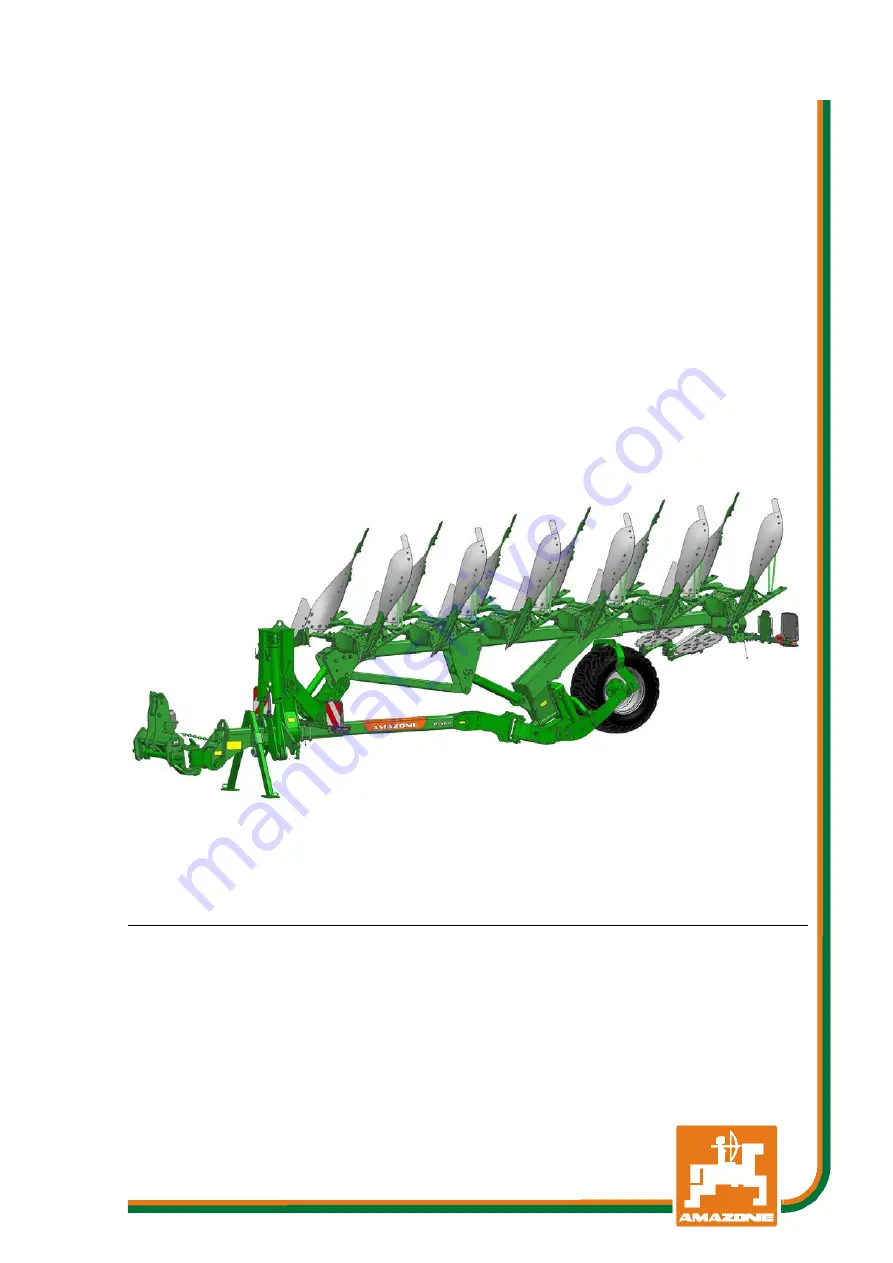
Hektor
Trailed reversible plough
MG6213 BAG0186.1 07.19 Printed in Germany
Read and observe this
operating manual before using
the implement for the first time!
Keep it in a safe place for future
use!
en
Page 1: ...anual az Hektor Trailed reversible plough MG6213 BAG0186 1 07 19 Printed in Germany Read and observe this operating manual before using the implement for the first time Keep it in a safe place for fut...
Page 2: ...only harm himself but also make the mistake of blaming the machine for the reason of a possible failure instead of himself In order to ensure a good success one should go into the mind of a thing or...
Page 3: ...g Permissible total weight kg Manufacturer s address AMAZONEN WERKE H DREYER GmbH Co KG Postfach 51 D 49202 Tel E mail Hasbergen Germany 49 0 5405 50 1 0 amazone amazone de Spare part orders Spare par...
Page 4: ...available in certain markets The sales documents provide information on the equipment of your implement or consult your dealer for more detailed information All information in this operating manual c...
Page 5: ...formation Only after careful reading will you be able to benefit from the full scope of your newly purchased implement Please ensure that all the implement operators have read this operating manual be...
Page 6: ...ast 24 4 1 1 Data required for the calculation 25 4 1 2 Calculation of the required minimum ballasting at the front GV min of the tractor for assurance of the steering capability 26 4 1 3 Calculation...
Page 7: ...ulic accumulator 55 10 5 Checking the condition of the shares and wear parts 56 10 6 Checking the shear bolts 56 10 7 Checking the support wheel 57 10 7 1 Changing the support wheel 57 10 7 2 Check be...
Page 8: ...while keeping safety and potential dangers in mind and observing the operating manual Intended use also covers Compliance with all the instructions in this operating manual Execution of inspection and...
Page 9: ...e state to replace damaged warning symbols Obligations of the user Before starting work anyone charged with working with on the implement is obliged to comply with the basic workplace safety instructi...
Page 10: ...e operator at the latest on conclusion of the contract Guarantee and liability claims for damage to people or property will be excluded if they can be traced back to one or more of the following cause...
Page 11: ...jury WARNING Indicates a medium risk which could result in death or serious physical injury if not avoided If the instructions are not followed then this may result in death or serious physical injury...
Page 12: ...e safety equipment regularly 2 4 Safety and protective equipment Before starting up the implement each time all the safety and protection equipment must be properly attached and fully functional Check...
Page 13: ...ucted in their assigned tasks and in the possible risks in the case of improper behaviour have been trained if necessary and have been informed about the necessary protective equipment and measures 3...
Page 14: ...start up Carefully fix and secure larger assembly groups to lifting gear when carrying out replacement work Regularly check that bolted connections are firmly secured and tighten if necessary When th...
Page 15: ...he operating permit remains valid according to the national and international regulations If you use wear and spare parts from third parties there is no guarantee that they have been designed and manu...
Page 16: ...rolling away 10 Before starting vehicle check its road and operating safety 11 Stickers concerning safety warnings must be kept clean and legible If damaged they must be replaced 12 Couple the impleme...
Page 17: ...tor and battery 32 The hydraulic system is under pressure 33 When connecting the hydraulic hoses to the tractor s hydraulic system ensure that the hydraulics are depressurised on both the tractor side...
Page 18: ...s Field 1 is a symbol describing the danger surrounded by triangular safety symbol Field 2 is a symbol showing how to avoid the danger Warning symbols explanation The column Order number and explanati...
Page 19: ...eral safety instructions 2 14 1 Positions of warning symbols and other labels Warning symbols The following diagrams show the arrangement of the warning symbols on the implement Hektor BAG0186 1 07 19...
Page 20: ...m is running MD 079 Risk of materials or foreign objects being flung away by or out of the implement These dangers can cause extremely serious and potentially fatal injuries Keep a sufficient safety d...
Page 21: ...ately MD 100 This symbol indicates attachment points for lifting gear for loading the implement MD101 This symbol indicates application points for using lifting gear jack MD 102 Dangerous situations f...
Page 22: ...General safety instructions MD 114 This pictogram indicates a lubrication point MD 199 The maximum operating pressure of the hydraulic system is 210 bar 22 Hektor BAG0186 1 07 19...
Page 23: ...or 8 1000 8 furrows 3 610 kg Stone release NON STOP hydraulic compact accumulator Hektor 5 1 1000 S 6 furrows 100 cm 82 cm 78 cm 3 500 kg Hektor 6 1000 S 6 furrows 3 480 kg Hektor 6 1 1000 S 7 furrows...
Page 24: ...he connected machine This information is only valid for the Federal Republic of Germany If having tried all possible alternatives it is not possible to comply with the axle loads and or the permissibl...
Page 25: ...hnical data of tractor and front machine mounting or front ballast or measurement a1 m Distance from the centre of the front axle to the centre of the lower link connection See tractor operating manua...
Page 26: ...rating manual in the table Section 7 1 1 7 4 1 4 Calculation of the actual total weight of the combined tractor and machine H L V tat F T G G Enter the numeric value for the calculated actual total we...
Page 27: ...The actually calculated values must be less than or equal to the permissible values WARNING Risk of crushing cutting being caught or drawn in or impact through insufficient stability and insufficient...
Page 28: ...nd can impair the steering and braking behaviour Moreover the pulling force transfer slippage is improved with four wheel drive tractors Lifting rods The lifting rods H must be set to the same length...
Page 29: ...equipment Front lighting 1 Reflector white Rear lighting 1 Reflector yellow 2 Warning signs 3 Brake light and direction indicator 4 Reflector triangular 5 Number plate holder with lighting 6 Maximum...
Page 30: ...sk of tipping when the plough is being dismounted It is therefore essential that the implement be secured with stand supports The plough must only be mounted and dismounted on firm level ground 5 1 Un...
Page 31: ...spring cotter pins 4 Lower the implement and thus relieve the running gear wheel 5 Put down the implement from transport position onto the two jacks 6 Close the stop tap for the lifting hydraulic syst...
Page 32: ...Coupling and uncoupling the implement 32 Hektor BAG0186 1 07 19...
Page 33: ...lustrate the respective hydraulic function The tractor control unit must be used in different types of activation depending on the hydraulic function Latched for a permanent oil circulation Tentative...
Page 34: ...neral oils with bio oils Push the hydraulic connector s into the hydraulic sockets until you feel them lock Check the coupling points of the hydraulic hose lines for a correct tight seat Coupled hydra...
Page 35: ...and the plough is essential Prior to connecting and disconnecting the implement to the three point suspension place operating equipment in such a position as to prevent unintentional lifting or lower...
Page 36: ...implement during work or road transport is not permitted The road traffic regulations must be observed at all times when using public roads 1 Lift the implement completely using the running gear and t...
Page 37: ...the bolt back in and tighten it 5 Retighten the large bolt see top image 6 Repeat the procedure for all of the elements 7 Loosen the bolt 3 8 Remove the bolt 4 and set the plough beam carrier to the...
Page 38: ...he first furrow 4 Turn at the end of the field and rotate the plough 5 Drive with the tractor wheels in the furrow The tractor is now standing on a slant and you must check the working depth and the p...
Page 39: ...ymmetrically on the left and right using the setting spindles 1 The landsides and plough beams 2 must be perpendicular to the ground 1 Front pitch stop To be able to turn the setting spindles briefly...
Page 40: ...age and that the bolt is securely tightened again 2 Adjusting the lateral distance to the plough body landside The distance between the side of the disc and the plough body landside should be between...
Page 41: ...round When adjusting rocker bar A make sure that the cogs engage smoothly and that bolt S1 is securely tightened The distance between the side of the disc and the ploughing tackle should be between 1...
Page 42: ...here are large amounts of crop residues If the fertiliser skimmers interfere due to large amounts of crop residues you can take them off by removing the 2 bolts Use on stony soils is not advised no st...
Page 43: ...accumulator or central adjustment works in the same way as the mechanical stone release the only difference being that instead of the leaf springs a hydraulic cylinder with a connected hydraulic accu...
Page 44: ...re completely using the pressure control tube The system is under high pressure Risk of overturning Before reducing the system pressure the plough must be coupled or suitably supported Mode of operati...
Page 45: ...l 140 bar 8 2 1 Hydraulic stone release with central pressure setting The tripping pressure can be adjusted for all shares together while driving via the grey tractor control unit Before coupling and...
Page 46: ...ith pressure gauge Setting the tripping pressure 1 Couple the intended pressure control hose to the tripping unit and tractor 2 Open the stop tap on the hydraulic cylinder position I 3 Actuate the tra...
Page 47: ...Rotating the plough DANGER The plough sweeps out when it is rotated Direct people out of the danger area Check the immediate area before rotating On the headlands 1 When reaching the headland lift the...
Page 48: ...arry out maintenance or repair work under moving machine parts that are in a raised position if such parts are secured with suitable positive fit locking devices against accidental lowering Regular an...
Page 49: ...g work on the implement The implement may only be operated with the protective devices equipped ex factory Hydraulic cylinders may only be opened by authorised persons The mounting category pin diamet...
Page 50: ...efore lubrication so that no dirt is pressed into the bearings Press the dirty grease completely out of the bearings and replace with new grease Overview of lubrication points Lubrication point Number...
Page 51: ...Cleaning maintenance and repair Hektor BAG0186 1 07 19 51...
Page 52: ...ing agents Cleaning with a high pressure cleaner steam jet Always observe the following points when using a pressure washer steam jet for cleaning Do not clean any electrical components Do not clean a...
Page 53: ...k Hydraulic system Check for leaks Check for defects on the hose lines 59 Daily Component Servicing work see page Workshop work Whole implement Check for visible defects Clean after operation and prot...
Page 54: ...plough with hydraulic stone release in working position the implement will fall over Support the implement or couple it to the tractor The system is only depressurised when the implement in working p...
Page 55: ...DANGER During ploughing operation overstraining can cause components to break and be flung away at high speed The piston accumulator is under high pressure Ensure that nobody is standing close to the...
Page 56: ...mulator The gas pressure side may only be set by the dealer and must be checked once annually Pre tensioning pressure nitrogen 90 bar Min working pressure hydr oil 90 bar The maximum pressure set must...
Page 57: ...s 600Nm 10 7 1 Changing the support wheel 1 Put down the coupled implement in working position on the shares 1 Lift the support wheel from the ground using a lifting jack 2 Loosen the axle attachment...
Page 58: ...to the next hole max 30 5 Insert the cotter pin and bend it up slightly 6 Replenish the dust cap with some long term grease and pound or screw it into the wheel hub 10 8 Storage overwintering After u...
Page 59: ...draulic hose lines using your hand or fingers Escaping high pressure fluid hydraulic fluid may pass through the skin and ingress into the body causing serious injuries If you are injured by hydraulic...
Page 60: ...two years Even with proper storage and approved use hoses and hose connections are subject to natural aging thus limiting the duration of use However it may be possible to specify the length of use fr...
Page 61: ...er layer up to the ply e g scouring points cuts cracks Brittleness of the outer layer crack formation of the hose material Deformations that do not match the natural shape of the hose Both in a depres...
Page 62: ...ctive covers Cover sharp edged components The approved bending radii may not be exceeded When connecting a hydraulic hose line to moving parts the hose length must be appropriate so that the smallest...
Page 63: ...485 M 18x1 5 325 460 550 M 20 30 410 580 690 M 20x1 5 460 640 770 M 22 32 550 780 930 M 22x1 5 610 860 1050 M 24 36 710 1000 1200 M 24x2 780 1100 1300 M 27 41 1050 1500 1800 M 27x2 1150 1600 1950 M 30...
Page 64: ...wheels higher up Lower the hydraulic system Replace the shares or use chisel shares Plough bodies work at different depths Correct the working depth adjust Correct the pitch Plough works unevenly Shea...
Page 65: ...Hydraulic diagram 12 Hydraulic diagram Hektor BAG0186 1 07 19 65...
Page 66: ......