The mower unit
52
Groundkeeper Jumbo SMARTCUT BAF0008.3 05.17
Page 1: ...anual az GROUNDKEEPER GHS JUMBO SMARTCUT MG5081 BAF0008 3 05 17 Printed in France Please read and follow this op erating manual before putting the machine into operation Keep it in a safe place for fu...
Page 2: ...by itself The person concerned would not only harm himself but also make the mistake of blaming the machine for the reason of a possible failure instead of himself In order to ensure good success one...
Page 3: ...Manufacturer s address AMAZONE S A FORBACH 17 rue de la Verrerie BP 90106 F 57602 Phone Fax E mail Forbach France 33 0 3 87 84 65 70 33 0 3 87 84 65 71 forbach amazone fr Spare part orders Spare parts...
Page 4: ...e into operation Only after careful reading will you be able to benefit from the full scope of your newly purchased machine Please ensure that all the machine operators have read this operating manual...
Page 5: ...observed 23 2 15 Safety conscious working 23 2 16 Safety information for users 24 2 16 1 General safety and accident prevention information 24 2 16 2 Hydraulic system 27 2 16 3 Electrical system 28 3...
Page 6: ...48 6 4 Scarifying 49 6 5 Mulching 51 6 6 Collecting 53 6 7 Emptying the catcher 53 7 Adjusting the cutting height 54 7 1 Front roller accessory 55 8 Cleaning the machine 56 9 Maintenance are care 57...
Page 7: ...pecified in the operating manual are always viewed in the direction of travel 1 3 Diagrams used Instructions for action and reactions Tasks to be carried out by the user are presented as numbered in s...
Page 8: ...legible state To replace damaged warning symbols If you still have queries please contact the manufacturer Obligations of the user Before starting work anyone charged with working with on the ma chine...
Page 9: ...le These shall be available to the operator at the latest on the comple tion of the contract Guarantee and liability claims for damage to peo ple or goods will be excluded if they can be traced back t...
Page 10: ...lt in imme diate death or serious physical injury WARNING Indicates a medium risk which could result in death or extreme ly serious physical injury if not avoided If the instructions are not followed...
Page 11: ...nt regularly 2 4 Safety and protection equipment Before each commissioning of the machine all the safety and protec tion equipment must be properly attached and fully functional Check all the safety a...
Page 12: ...pany 2 Instructed persons are those who have been instructed in their assigned tasks and in the possible risks in the case of improper behaviour have been trained if necessary and have been in formed...
Page 13: ...nd the hydraulic system against unintentional start up Carefully fix and secure larger subassemblies to lifting gear when carrying out replacement work Check all the screw connections for a firm seat...
Page 14: ...t the operating permit retains its validity in accordance with national and international regulations If you use wear and spare parts from third parties there is no guarantee that they have been desig...
Page 15: ...he following diagrams show the arrangement of the warning symbols on the machine Always keep all the warning symbols of the machine clean and in a legi ble state Replace illegible warning symbols You...
Page 16: ...a symbol showing how to avoid the danger Warning symbols explanation The column Order number and explanation provides an explanation of the neighbouring warning symbol The description of the warning...
Page 17: ...ody from hands or arms Never open or remove protective equipment from chains or belt drives while the tractor engine is running and the PTO shaft is connected hydraulic drive is engaged or the ground...
Page 18: ...serious injuries anywhere on the body or even death Before spending time in the danger area under neath raised machine parts secure the raised parts against descending unintentionally To do this use t...
Page 19: ...dy if hydraulic fluid escaping at high pressure passes through the skin and into the body Never attempt to plug leaks in hydraulic lines using your hand or fingers Read and understand the information...
Page 20: ...re any intervention in the machine Depending on the type of intervention read and understand the information in the rele vant sections of the operating manual MD 104 Risk of crushing of torso due to s...
Page 21: ...maximum drive speed 540 rpm and direction of rotation of the drive shaft on the machine side MD 170 Risk of being crushed drawn in or caught by unprotected moving machine parts as a re sult of missin...
Page 22: ...as a result of standing in the tipping area when the loading bed has been raised This hazard can cause extremely serious and potentially fatal injuries It is prohibited to stand in the tipping area w...
Page 23: ...ple through non secured working areas Failure of important machine functions Failure of prescribed methods of maintenance and repair Danger to people through mechanical and chemical impacts Risk to en...
Page 24: ...ty and weather conditions the driving char acteristics of the tractor and the connected machine Connecting and disconnecting the machine Only connect and transport the machine with tractors suitable f...
Page 25: ...ore starting work ensure that you understand all the equip ment and actuation elements of the machine and their function There is no time for this when the machine is already in opera tion Do not wear...
Page 26: ...rescribed brake delay for the loaded vehicle combination tractor plus connected machine Check the brake power before moving off When turning corners with the machine connected take the broad load and...
Page 27: ...arking brake Remove the ignition key Have the hydraulic hose line checked at least once a year by a specialist for proper functioning Replace the hydraulic hose line if it is damaged or worn Only use...
Page 28: ...tact with earth may cause an explosion Risk of explosion avoid the production of sparks or the presence of naked flames in the vicinity of the battery The machine can be equipped with electronic compo...
Page 29: ...tive 2006 42 EC and corresponding supplementary guidelines 3 3 Details required for enquiries When ordering special optional equipment and spare parts please always quote the machine number of your Gr...
Page 30: ...500 l 1 020 kg 2 60 x 2 50 x 1 65 Unloading height approx 2 20 m GHS type 1500 1800 2100 Tyres front 270 x 185 270 x 185 270 x 185 Rear tyres 4x 16x6 5 8 4x 16x6 5 8 4x 16x6 5 8 Front tyre pressure 2...
Page 31: ...pecified by the manufacturer concerning operation servicing and maintenance as well as the exclusive use of genuine AMAZONE spare parts This Amazone Groundkeeper Jumbo may only be used serviced and ma...
Page 32: ...issing Replacements will only be made if claims are submitted promptly to the haulage company Please check that all the parts listed on the despatch note have been delivered Before starting up complet...
Page 33: ...of the three point system on the machine matches the mount category of the tractor CAT I or II Release the fastener on the lower link sockets Fig 5 1 Bring the lower link socket into the required pos...
Page 34: ...l pins using the appropriate securing plugs Attach the PTO shaft to the tractor s universal joint shaft CAUTION Make sure that the PTO shaft is the correct length otherwise the tractor or the machine...
Page 35: ...0 with or without freewheel for tractors with max 40 HP output Walterscheid W 2400 with or without freewheel for tractors with outputs higher than 40 HP If you have a tractor without a double clutch f...
Page 36: ...ft tubes side by side and check whether the PTO shaft tubes provide a guaranteed sliding profile overlap of at least 40 of the LO both when the machine is lowered and raised 2 When pushed together the...
Page 37: ...iversal joint shaft slowly when the tractor engine is running at low revs 5 3 Groundkeeper Jumbo gearbox input speed The gearbox on the Groundkeeper Jumbo has a universal joint shaft connection The ma...
Page 38: ...tuck on the implement for the markings that illustrate the respective hydraulic function The tractor control unit must be used in different types of activa tion depending on the hydraulic function Lat...
Page 39: ...ot mix any mineral oils with biological oils Observe the maximum permissible hydraulic fluid pressure of 200 bars Only couple clean hydraulic connectors Plug the hydraulic plug s into the hydraulic so...
Page 40: ...d and allows the machine to be op erated using only two hydraulic lines and one additional electrical connection Connection 1 permanent pressure connection required hydraulic power 200 bar 40 l min Co...
Page 41: ...d simultaneously Float position means that the mower takes control of ground tracking with the rear wheels only providing a support function while for the most part equalising differences in ground le...
Page 42: ...onds to lower when full The lowering speed can be adjusted using the lowering throttle in the hopper s hydraulic actuation circuit mounted in the frame next to the gearbox see Fig 5 4 2 and Fig 5 4 3...
Page 43: ...around the rotor from so called clip bolts 6 1 Fitting the mowing and scarifying tools There are 5 different tool arrangements shown in Table 11 If the mowing or scarifying blades are worn on one sid...
Page 44: ...a terial dry conditions 100 scarifying blade Collecting scarified ma terial wet conditions 100 wing blade long H77 100 scari fying blade Mowing scarifying and collecting in one opera tion dry conditio...
Page 45: ...ir Pair Working width 1 50 m 83 pcs 82 pcs 82 pcs 42 pairs 82 pairs 82 pairs Working width 1 80 m 100 pcs 100 pcs 100 pcs 50 pairs 100 pairs 100 pairs Working width 2 1 m 116 pcs 116 pcs 116 pcs 58 pa...
Page 46: ...wing manner Attach the machine to a tractor Fully raise the catcher Fit the safety support on the upper right hand lifting cylinder of the catcher Fig 6 1 5 Turn off the tractor engine Unlock the inte...
Page 47: ...The mower unit Groundkeeper Jumbo SMARTCUT BAF0008 3 05 17 47...
Page 48: ...to limit position Mowing slide plate down to limit position The baffle plate can be accessed by raising and securing the hop per then folding up the cover flap CAUTION Only carry out work on the machi...
Page 49: ...between the pairs of curved mowing blades If the turf has already been cut short only the straight blades are fitted The combination of mowing and scarify ing blades produces the best suction effect...
Page 50: ...hine being damaged 2 Only one type of scarifying blade may be used Risk of imbal ance 3 If a high proportion of soil content is produced from scarify ing only fill the catcher to approximately half wa...
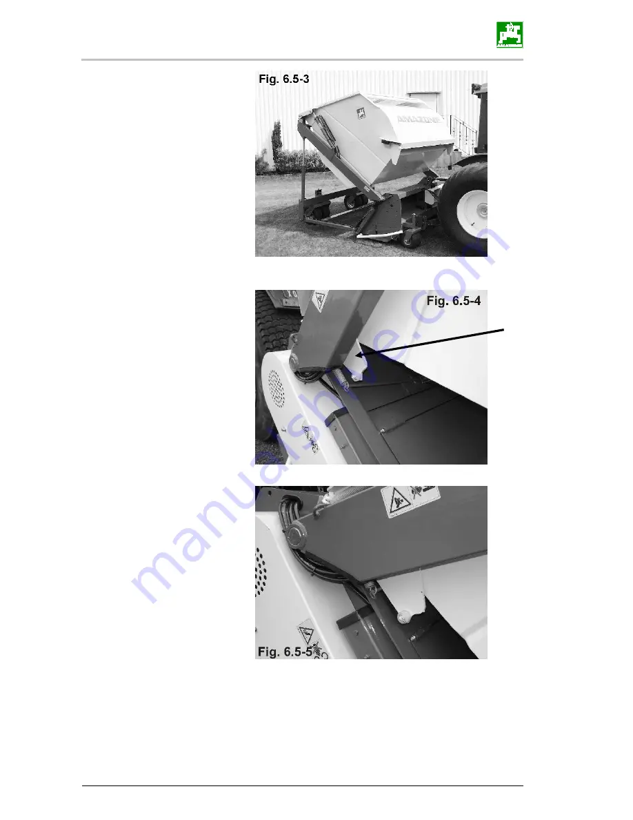
Page 51: ...osed during mowing To make this adjustment proceed as follows Extend the hydraulic system of the rear guide wheels and lower the three point system Fig 6 5 2 Raise the hopper Fig 6 5 3 Lower the hoppe...
Page 52: ...The mower unit 52 Groundkeeper Jumbo SMARTCUT BAF0008 3 05 17...
Page 53: ...s to be emptied Fig 6 3 While the indicator is in the lower position cuttings can continue to be collected When the pointer starts to approach or has reached the upper position the catcher must be emp...
Page 54: ...and increase the cutting height see Fig 7 1 2 You can adjust the height of the guide wheels by removing the spacer sleeves and repositioning them see Fig 7 2 To adjust the wheels it is necessary to r...
Page 55: ...ory A front roller is available as a special accessory for scarifying on une ven terrain This is mounted in the brackets of the front guide wheels Fig 7 1 1 To adjust the height the lynch pin and the...
Page 56: ...8 Cleaning the machine The machine can on occasion become heavily soiled especially when mowing and scarifying wet grass which is also sometimes inter spersed with earth In such cases it is recommende...
Page 57: ...lled with SAE 90 transmission oil capacity 0 45 l if required 9 2 Lubrication points Depending on the intensity of work the following areas should be regularly lubricated with multipurpose grease Catc...
Page 58: ...oundkeeper Jumbo SMARTCUT BAF0008 3 05 17 Pivot points of the attachment fork Fig 9 2 6 Adjusting crank of rear cage roller Fig 9 2 7 Universal joint of friction coupling remove weighing frame and dri...
Page 59: ...Maintenance are care Groundkeeper Jumbo SMARTCUT BAF0008 3 05 17 59...
Page 60: ...e belt depends on the transmission forces of the PTO shaft drive and type of use 9 4 Extended periods of downtime If the machine is not to be used for a long period of time it is recom mended that bef...
Page 61: ...moving or fitting tyres the tyres must always be fully deflated a split tyre wall can fly apart with explosive force during removal Carry out a test drive to check the damping performance of the rear...
Page 62: ...he rear guide wheels hydraulic system and the tractor s lower link arms In doing so the machine must always be in a horizontal position i e not tilting excessively forwards or back wards Fig 10 1 and...
Page 63: ...Groundkeeper Jumbo SMARTCUT BAF0008 3 05 17 63...
Page 64: ...17 rue de la Verrerie BP 90106 F 57602 FORBACH Cedex France Tel 33 0 3 87 84 65 70 Telefax 33 0 3 87 84 65 71 e mail forbach amazone fr http www amazone fr Branch plants D 27794 Hude D 04249 Leipzig G...