Amana NTW5400T Technical Education Download Page 21

2-

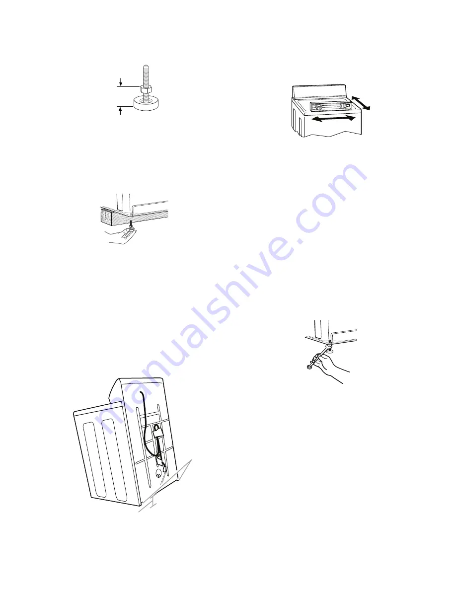
3.   Screw the feet into the threaded holes at 

the  front  corner  of  the  washer  until  the 

nuts touch the washer. Twist the feet to 

install.


NOTE:

 Do not tighten the nuts until the 

washer is level.

2.   Screw the locknut onto each foot to within 

1

˝

 (2.5 cm) of the foot base.

"

1

2.5 cm)

(

4.   Tilt  the  washer  back  and  remove  the 

wood block. Gently lower the washer to 

the floor.

Steps in final location

1.   Slide the washer to its final location.
2.   Tilt  the  washer  forward  until  the  rear  of 

the  washer  is  at  least  4

˝

  (10.2  cm)  off 

the  floor.  You  may  hear  the  self-adjust

-

ing  rear  feet click  into  place.  Lower  the 

washer to the floor.

3.   Check  the  levelness  of  the  washer  by 

placing  a  level  on  the  top  edges  of  the 

washer,  first  side  to  side,  then  front  to 

back.

4.   If the washer is not level, move the wash

-

er out slightly, tip back, prop up the front 

of  the  washer  with  the  wood  block  and 

adjust the feet up or down as necessary 

by twisting the feet. Turn the feet clock

-

wise to raise the washer or counterclock

-

wise to lower the washer. Repeat steps 1 

through 4 until washer is level.

5.   After  the  washer  is  in  the  final  location 

and  level,  use  a  9/16

˝

  or  14  mm  open-

end  wrench  to  turn  the  nuts  counter

-

clockwise on the feet tightly against the 

washer cabinet.


IMPORTANT:

  If  the  nuts  are  not  tight 

against the washer cabinet, the washer 

may vibrate.

A. Self-adjusting feet

A

4"

(10.2 cm)

Summary of Contents for NTW5400T

Page 1: ...JOB AID 8178662 AL 1 TOP LOAD WASHER TECHNICAL EDUCATION MODELS NTW5200T NTW5240T NTW5400T NTW5500T NTW5505T NTW5640T NTW5700T NTW5705T NTW5800T...

Page 2: ...iring Diagram used in this Job Aid is typical and should be used for training purposes only Always use the Wiring Diagram supplied with the product when servicing the washer GOALS AND OBJECTIVES The g...

Page 3: ...Power Supply Cord 4 2 Removing The Lid Switch 4 5 Removing The Bleach Dispenser Wax Motor 4 6 Removing The Rear Panel Components 4 8 Removing The Pump And Motor 4 11 Removing The Agitator And Transmis...

Page 4: ...iv NOTES...

Page 5: ...can kill or hurt you and others All safety messages will follow the safety alert symbol and either the word DANGER or WARNING These words mean All safety messages will tell you what the potential haza...

Page 6: ...Load G Gas F Front Load H Horizontal W Work Space V Vertical E Electric PRODUCT W Washer P Pedestal D Dryer B Combo T Thin Twin C Compact SERIES 1 Innovation 6 Oasis 2 Commercial 7 Merloni 3 Compact...

Page 7: ...1 MODEL SERIAL NUMBER LABEL AND TECH SHEET LOCATIONS The Model Serial Number Label and Tech Sheet locations are shown below Model Serial Number Label Tech Sheet Behind Console...

Page 8: ...nse No EOC Anti Microbial Product Protection On Console Anti Microbial Parts Tub Ring Agitator Base No Quiet NTW5240T Super Capacity J line Console Shape New Amana Bladed Knobs Amana Formed Badge J li...

Page 9: ...C No Anti Microbial Product Protection On Console No Anti Microbial Parts Tub Ring Agitator Base No Quiet NTW5500T Super Capacity Plus J line Console Shape New Amana Bladed Knobs Amana Formed Badge J...

Page 10: ...No Anti Microbial Product Protection On Console No Anti Microbial Parts Tub Ring Agitator Base No Quiet NTW5640T Super Capacity Plus J line Console Shape New Amana Bladed Knobs Amana Formed Badge J li...

Page 11: ...Anti Microbial Product Protection On Console Anti Microbial Parts Tub Ring Agitator Base Quiet FM NTW5705T Super Capacity Plus J line Console Shape New Amana Bladed Knobs Amana Formed Badge Wide Open...

Page 12: ...s 2 Speed Motor 5 Speed Combo ATC 4 Smart Temps Variable Water Level 5 Position Speed Select Smart Slate Porcelain Basket Painted Top Xtra Roll Plus Agitator No Detergent Dispenser Dump Bleach Agitato...

Page 13: ...2 cm diameter to 1 in diameter standpipe 2 5 cm diameter standpipe adapter Part No 280130 Overhead sewer Standard 20 gal 76 L 39 in 99 cm tall drain tub or utility sink sump pump and connectors availa...

Page 14: ...ling the washer on carpeting is not recommended A sturdy floor to support the washer weight washer water and load of 315 lbs 143 kgs Do not store or operate your washer in tem peratures at or below 32...

Page 15: ...m from the bottom of the washer To avoid siphoning no more than 8 20 3 cm of drain hose should be below the top of the washtub Secure drain hose with beaded tie strap Laundry tub drain system view C T...

Page 16: ...th a qualified electrician if you are not sure the washer is properly grounded Do not have a fuse in the neutral or ground circuit GROUNDING INSTRUCTIONS For a grounded cord connected washer This wash...

Page 17: ...po sition and not tilted before removing the shipping material 3 Locate the yellow shipping materials on the rear of the machine near the bottom Followthestepsforyourparticular model either the one w...

Page 18: ...d to your washer and is stored inside the washer cabinet Remove drain hose from washer cabinet Gently pull the corrugated drain hose out of the washer from the top of the hose Continue to pull the hos...

Page 19: ...the hot water faucet and that the cold water hose is connected to the cold water faucet To keep drain water from going back into the washer Do not force excess drain hose into stand pipe Hose should b...

Page 20: ...ng material from the power cord Drape the power cord over the console 2 Remove any cardboard used to move washer 4 Using pliers tighten the couplings with an additional two thirds turn NOTE Do not ove...

Page 21: ...ace Lower the washer to the floor 3 Check the levelness of the washer by placing a level on the top edges of the washer first side to side then front to back 4 If the washer is not level move the wash...

Page 22: ...e ground prong Do not use an adapter Do not use an extension cord Failure to follow these instructions can result in death fire or electrical shock WARNING COMPLETE THE INSTALLATION 1 Check the electr...

Page 23: ...ach 2 Drop a sorted load of clothes loosely into your washer Load evenly to maintain washer bal ance Mix large and small items Items should move easily through the wash water Load only to the top of t...

Page 24: ...every load or use less of it in each load Style 1 With liquid fabric softener dis penser on some models Use only liquid fabric softener in this dispenser Pour measured liquid fabric softener into the...

Page 25: ...l wash temperatures agitation times and agitation spin speeds based on the Fabric Selectsetting Thecontrolsprovideshigher wash temperatures for more aggressive heavy duty cycles and slightly lower tem...

Page 26: ...ose failure Periodically in spect and replace inlet hoses if bulges kinks cuts wear or leaks are found When replacing your inlet hoses mark the date of replacement on the label with a permanent marker...

Page 27: ...he front feet should be properly installed and the nuts tightened Reset the rear leveling legs if needed See Level the Washer page 2 8 Check household plumbing for leaks BASKET CROOKED Was the washer...

Page 28: ...r gap See Secure the Drain Hose page 2 8 WASH RINSE TEMPERATURE NOT WHAT I SELECTED Are the hot and cold water inlet hoses reversed See Connect the Inlet Hoses page 2 7 for more information As your fr...

Page 29: ...to the rinse portion of a cycle only Do not drip fabric softener on clothes Isthereaboveaverageiron rust inwater You may need to install an iron filter Did you properly sort the load Sort dark clothe...

Page 30: ...snap or hook fasteners before washing Were strings and sashes tied to avoid tangling Wereitemsdamagedbeforewashing Mend rips and broken threads in seams before washing Did you overload the washer The...

Page 31: ...elow Rear Panel Front Panel Power Supply Cord Vacuum Break Water Inlet ATC Sensor Washer Motor Motor Start Capacitor Pump Agitator Bleach Dispenser Wax Motor Transmission Basket Drive Assembly Basket...

Page 32: ...E Timer Delay F Buzzer G A B C D E F G WARNING Console Screws 3 Rotate the console back so that you can access the components see above 1 Unplug washer or disconnect power 2 Remove the two screws fro...

Page 33: ...lay terminal d Remove the timer delay from the timer see step 4 6 To remove the water level pressure switch a Pull the pressure hose off the switch b Disconnect the wire connector from the switch term...

Page 34: ...move the power supply cord a Lift up on the locking tab and discon nect the power supply cord connector from the main harness b Press the locking tab and pull the strain relief and power supply cord o...

Page 35: ...e operating Failure to do so can result in death or electrical shock WARNING 3 Lift the locking tab and disconnect the main harness from the lid switch connec tor see the top right photo 4 Remove the...

Page 36: ...page 4 2 for the pro cedure 3 Disconnect the main harness connector from the lid switch connector 4 Use a screwdriver and unclip the left and right cabinet spring clips from the cabinet top 5 Rotate t...

Page 37: ...d remove bleach dispenser wax motor 11 Turn the bleach dispenser wax motor to unlock the tabs and pull the motor and seal out of the holder in the tub ring Tab Motor Tab Pry Tab Up On Retaining Ring P...

Page 38: ...n it back out of the way see page 4 2 for the pro cedure 3 Rotate the cabinet forward so you can access the rear panel components The following rear panel components are ser viced in this section Vacu...

Page 39: ...r Inlet ATC Sensor Screw Hot Red Connector Cold White Connector ATC Sensor OR WH Wire PK Wire 6 To remove the motor start capacitor a On the outside of the rear panel squeeze the locking tabs on the c...

Page 40: ...he locking tabs on the drain hose bucket and push the tabs out of their slots b Lift the two locking arms on the bucket to release the tabs c Open the bucket sections and remove the drain hose Tabs Dr...

Page 41: ...se b Loosen the two clamps from the tub outlet and drain hoses and pull the hoses off the pump c Release the two spring clips and pull the pump away from the motor REASSEMBLY NOTE Position the pump on...

Page 42: ...port the bottom of the motor with one hand to keep it from falling and pry the ends of the two spring clips off the motor with a screwdriver see the round inset below Spring Clip Screws Motor Wire Con...

Page 43: ...ispenser c Pull the barrier cap and rubber O ring out of the agitator Barrier Cap Rubber O Ring d Remove the 7 16 hex head bolt from the agitator and lift the agitator out of the washer tub Agitator B...

Page 44: ...he pump and motor see page 4 11 for the procedure Transmission Bolts Remove Transmission f Pull the transmission away from the washer and remove transmission g Remove the isolator from the motor coupl...

Page 45: ...er Clutch Retaining Ring Remove Clutch Retaining Clip l Use a pair of pliers and remove the pad assembly from the clutch drum m Inspect the inside contact surface of the drum for scratch marks or unev...

Page 46: ...4 16 n Remove the motor from the transmis sion see page 4 12 for the procedure o Remove the two 1 2 hex head bolts from the motor plate and remove the plate Motor Plate 1 2 Bolts...

Page 47: ...dure Spanner Wrench Spanner Nut Electrical Shock Hazard Disconnect power before servicing Replace all parts and panels before operating Failure to do so can result in death or electrical shock WARNING...

Page 48: ...e the bracket b Loosen the clamp and remove the end of the tub to pump hose from the bot tom of the outer tub see the top right photo c Unhook the tub springs from the left and right front tub spring...

Page 49: ...the basket drive from the support assembly Clutch Engagement Cam SERVICE NOTE While the basket drive is removed check for shaft wear using the procedure shown on page 5 6 Basket Drive Shaft Drive Blo...

Page 50: ...s Pry Off Suspension Pads Washer Base 1 Unplug washer or disconnect power 2 Tilt the cabinet forward and remove cabinet see page 4 6 for the proce dure 3 Remove the outer tub see pages 4 17 and 4 18 f...

Page 51: ...dures All tests checks should be made with a VOM or DVM having a sensitivity of 20 000 ohms per volt DC or greater Check all connections before replacing com ponents looking for broken or loose wires...

Page 52: ...r to the R x 1 scale NOTE To activate the pressure switch blow into the pressure switch inlet 4 Touch the ohmmeter test leads to the test points indicated in the Water Level Switch Test Table The swit...

Page 53: ...t leads to the solenoid terminals The meter should indicate between 740 and 820 ATC Sensor Terminals Solenoid Terminals 3 To test the ATC sensor a Disconnect the wires from the sensor terminals b Touc...

Page 54: ...cate a low resis tance and then gradually fall to indicate a high resistance To repeat the test re verse the meter leads The result should be the same if the capacitor is good High Resistance Low Resi...

Page 55: ...U BK R OR CENTRIFUGAL SWITCH Y W BK W DRIVE MOTOR BK V BU OR R Motor Connector Electrical Shock Hazard Disconnect power before servicing Replace all parts and panels before operating Failure to do so...

Page 56: ...NING BASKET DRIVE SHAFT CHECKS Refer to page 4 17 for the procedure for ac cessing the basket drive 1 With the basket drive removed check for excessive wear on the shaft see the photo below Excessive...

Page 57: ...6 DIAGRAMS AND CHARTS WIRING DIAGRAM...

Page 58: ...6 TIMER SEQUENCE CHART...

Page 59: ...6 FUNCTION FUNCTION TIMER SEQUENCE CHART Cont d...

Page 60: ...6 CYCLE CHARTS Wash Action Switch Option Switch Soak Delay Temperature Switch...

Page 61: ...6 NOTES...

Page 62: ...6 NOTES...

Page 63: ...FOR TECHNICAL INFORMATION AND SERVICE POINTERS www servicematters com IN CANADA FOR PRODUCT SPECIFICATIONS AND WARRANTY INFORMATION CALL 1 800 461 5681 FOR TECHNICAL ASSISTANCE WHILE AT THE CUSTOMER...

Page 64: ......

Reviews: