background image

11

MATERIALS - INSTALLATIONS IN THE 

U.S.A

PVC, CPVC, or ABS pipe & fittings are typically used as 

venting and intake pipe materials. All 90° elbows must 

be medium or long radius types. A medium radius elbow 

should measure ~3-1/16” minimum from the plane of 

one opening to the center line of the other opening for 2” 

diameter pipe, and ~4-9/16” minimum for 3” pipe. 

In addition to these materials, Innoflue® by Centrotherm 

Eco Systems and PolyPro® by M&G Duravent are 

also approved vent and combustion air materials for 

installations in the U.S.A. Manufacturers Installation 

instructions for these products must be followed. These 

products have specific instructions for installing, joining 

and terminating. Do not mix materials or components of 

one manufacturer with materials or components of another 

manufacturer. Refer to the following chart for plastic pipe & 

fittings specifications

MATERIALS - INSTALLATIONS IN CANADA

All installations in Canada must conform to the 

requirements of CAN/CSA B149.1-15 code. All vent 

components, including primer and cement, must be listed 

to ULC S636. The certified pipe and fittings should be 

clearly marked with the ULC standard “S636”. The primer 

and cement used must be of the same manufacturer as 

the vent system. For Royal Pipe System 636; use GVS-

65 Primer (Purple) and GVS-65 PVC Solvent Cement. 

For IPEX System 636, use PVC/CPVC Primer, Purple 

or clear. Use PVC Solvent cement (Gray). For Canadian 

installations, ABS may be used as a combustion air pipe 

only. ABS is not an approved vent material in Canada. 

If ABS is used as a combustion air pipe, it must be CSA 

certified. Always follow the manufacturer’s instructions 

in the use of primer and cement. Do not use primer and 

cement around potential sources of ignition. Do not use 

primer or cement beyond its expiration date.

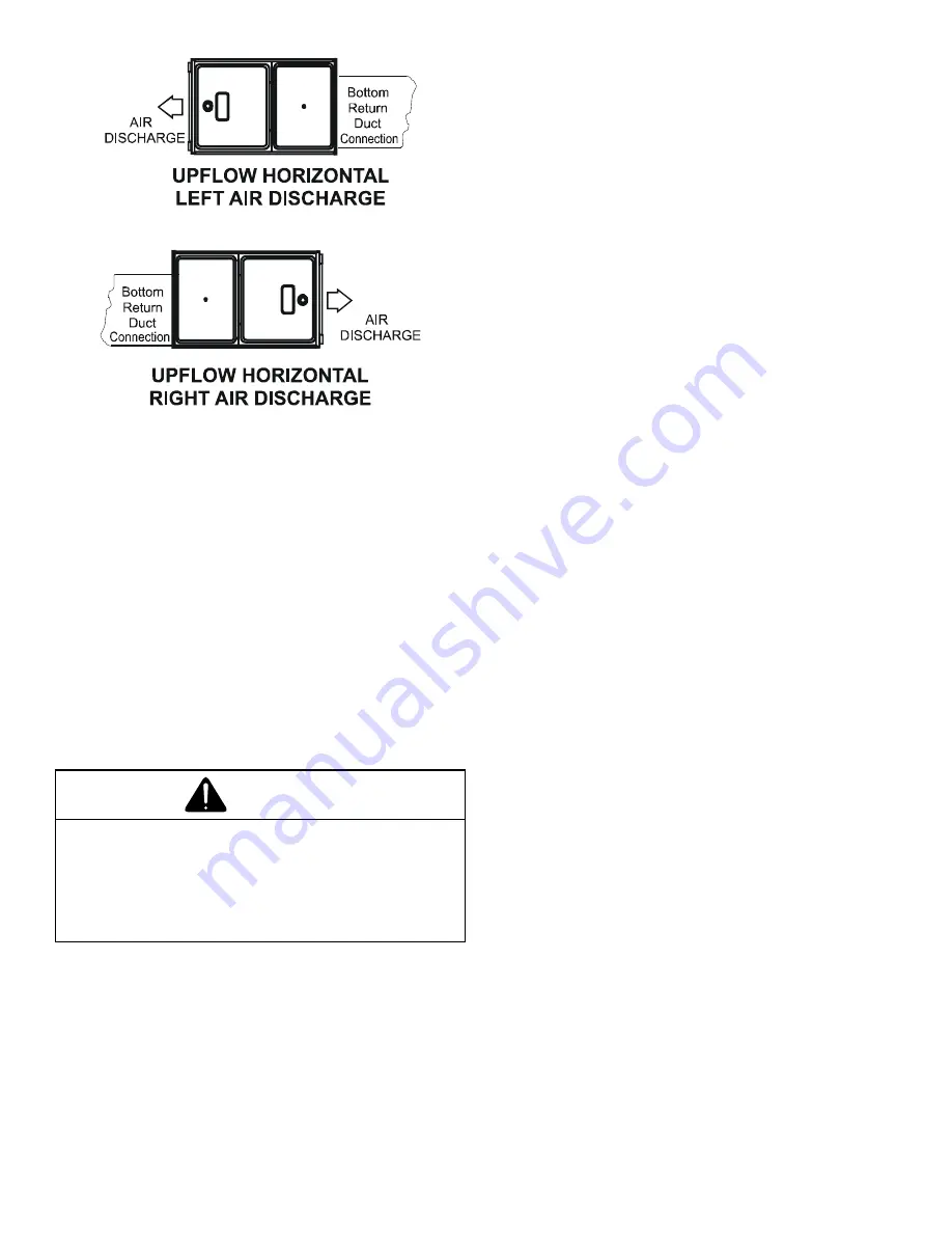
Figure 3B

Recommended Installation Positions 

Figure 3C 

Alternate Electrical and Gas Line Connections

This furnace has provisions allowing for electrical and gas 

line connectios through either side panel.  In horizontal 

applications the connections can be made either through 

the “top”or “bottom” of the furnace.

Drain Pan

A drain pan must be provided if the furnace is installed 

above a conditioned area.  The drain pan must cover the 

entire area under the furnace (and air conditioning coil if 

applicable).

Freeze Protection

Refer to 

Horizontal Applications and Conditions - Drain 

Trap and Lines.

WARNING

Possible property damage, personal injury or 

death may occur if the correct conversion kits 

are not installed. The appropriate kits must 

be applied to ensure safe and proper furnace 

opearation. All conversions must be performed 

by a qualified installer or service agency. 

VENT PIPE & COMBUSTION AIR

This manual will refer to the pipe that discharges products 

of combustion to the outdoors as the “vent” pipe or 

“flue” pipe. The pipe that supplies air for combustion 

to the furnace will be referred to as the “intake” pipe or 

“combustion air” pipe. 

This furnace is dual certified and may be installed as a 

non-direct vent (single pipe) or direct vent (dual pipe) 

appliance. 

Summary of Contents for CVC96 BB Series

Page 1: ...er if there is a direct conflict between existing practices and the content of this manual the precautions listed herein take precedence RECOGNIZE THIS SYMBOL AS A SAFETY PRECAUTION NOTE Please contac...

Page 2: ...te of Massachusetts 17 Condensate Drain Lines Drain Trap 18 Gas Supply and Piping 23 Propane Gas High Altitude Installations 23 Duct Work 26 Electrical Connections 29 Startup Procedure Adjustment 37 N...

Page 3: ...LOSION HAZARD AVERTISSEMENT RISQUE D INCENDIE OU D EXPLOSION Si les consignes de s curit ne sont pas suivies la lettre cela peut entra ner la mort de graves blessures ou des dommages mat riels Ne jama...

Page 4: ...trical connections circulating air temperature rise minimum or maximum CFM WARNING To prevent property damage personal injury or death due to fire do not install this furnace in a mobile home trailer...

Page 5: ...In their absence follow the latest edition of the National Fuel Gas Code NFPA 54 ANSI Z223 1 and or CAN CSA B149 1 15 Installation Codes local plumbing or waste water codes and other applicable codes...

Page 6: ...hylene printing inks chlorinated waxes or cleaners paint removers chlorine based swimming pool chemicals varnishes water softening chemicals hydrochloric acid carbon tetrachloride cements and glues de...

Page 7: ...g coil unit install the furnace upstream or in parallel with the cooling coil unit Premature heat exchanger failure will result if the cooling unit is placed ahead of the furnace For vertical upflow o...

Page 8: ...rmining the combustion air requirements for the appliances Clearance in accordance with local installation codes the requirements of the gas supplier and the manufacturer s installation instructions D...

Page 9: ...t hood relief opening after 5 minutes of main burner operation Use the flame of a match or candle 8 If improper venting is observed during any of the above tests the venting system must be corrected i...

Page 10: ...ier si la taille et l inclinaison par rapport l horizontale sont conformes aux exigences du National Fuel Gas Code ANSI Z223 1 NFPA 54 ou du Code d installation du gaz naturel et du propane CSA B149 1...

Page 11: ...tions ABS may be used as a combustion air pipe only ABS is not an approved vent material in Canada If ABS is used as a combustion air pipe it must be CSA certified Always follow the manufacturer s ins...

Page 12: ...GS F438 POLYPROPYLENE INNOFLUE CENTROTHERM POLYPRO DURAVENT PRIMER SOLVENT CEMENT PVC PRIMER F656 CPVC PRIMER F656 PVC SOLVENT CEMENT D2564 CPVC SOLVENT CEMENT F493 ABS SOLVENT CEMENT D2235 ABS PVC CP...

Page 13: ...lkway Non Direct Vent Vent Flue Termination Direct Vent Vent Flue Termination Forced Air Inlet Non Direct Vent Direct Vent Vent Flue Terminations Grade or Highest Anticipated Snow Level Vent Clearance...

Page 14: ...9 92 85 78 71 2 N A N A N A N A N A N A N A N A 3 113 106 99 92 85 78 71 64 2 N A N A N A N A N A N A N A N A 3 151 144 137 130 123 116 109 102 MV96C0403BN MVC96 CVC96 Direct Vent 2 Pipe and Non Direc...

Page 15: ...ned per material manufacturers specifications to prevent separation and flue gas leaks Figure 14 COMBUSTION AIR INTAKE OPTIONAL Not required for single pipe installation TEE OPTIONAL 96 MAX 3 MIN ROOF...

Page 16: ...n the exhaust vent and air intake terminations of adjacent units as with the exhaust vent and air intake terminations of a single unit If more than one direct vent furnace is to be installed horizonta...

Page 17: ...t Approved side wall horizontally vented gas fueled equipment does not provide the parts for venting the flue gases but identifies special venting systems the following requirements shall be satisfied...

Page 18: ...installed at a height no higher than the bottom of the furnace collector box to prevent air conditioning condensate from backing up into the furnace if the common drain was blocked Upflow Model Insta...

Page 19: ...er clamps and secure the hoses to drain trap The trap outlet faces the front of the furnace Secure the trap to the cabinet using two screws removed in step 2 by inserting the two screws through the la...

Page 20: ...ctor box drain port bottom in horizontal left position and install it on right side top collector box drain port 8 Refer to Field Supplied Drain section for instructions on field supplied nstalled dra...

Page 21: ...factory installed hose assemblies Remove the hose clamps to obtain the respective hoses needed for installation and install per the following directions 9 Install the non grommet end of hose 11 from...

Page 22: ...grommet end of hose 5 factory installed from outside the cabinet in the back drain hole 12 Insert 100 elbow in hose 5 and secure with a red clamp 13 Locate hose 4 and cut a cut off a 4 straight secti...

Page 23: ...Installations for details Consult the furnace Specification Sheet for a listing of appropriate kits The indicated kits must be used to insure safe and proper furnace operation All conversions must be...

Page 24: ...used to reach the outside of the cabinet A semi rigid connector to the gas piping may be used from there Use listed gas appliance connectors in accordance with their instructions Connectors must be fu...

Page 25: ...reach the outside of the cabinet to seal the grommet cabinet penetration A semi rigid connector to the gas piping can be used outside the cabinet per local codes 1 2 NPT pipe and fittings are require...

Page 26: ...n the unit and the utility room wall Never use a room closet or alcove as a return air chamber When furnace duct s supply air outside the space containing the furnace a return air duct must terminate...

Page 27: ...is in the full heat or cool position Checking Duct Static WARNING Never allow the products of combustion including carbon monoxide to enter the return duct work or circulation air supply Refer to you...

Page 28: ...16 X 25 Top Return CVC960804CN 2 10 X 20 or 1 16 X 25 Top Return CVC961005CN 2 14 X 20 or 1 20 X 25 Top Return CVC961205DN 2 14 X 20 or 1 20 X 25 Top Return Larger filters may be used filters may als...

Page 29: ...AL RETURN GRILLE FILTER SUPPORT BRACKET Field Supplied Possible Upright Counterflow Filter Locations Figure 45 Electrical Connections WARNING High voltage To avoid the risk of electrical shock wiring...

Page 30: ...rom the furnace ground screw located inside the furnace junction box all the way back to the electrical panel NOTE Do not use gas piping as an electrical ground To confirm proper unit grounding turn o...

Page 31: ...input from the thermostat Internal algorithms will control all available cooling and heating stages including dual fuel operation based on these inputs Any single stage 24VAC thermostat can be used F...

Page 32: ...greater than 50 for high stage operation 4 Confirm thermostat heating and cooling calls function proprly with equipment Quick Start Guiide For Non Communicating Outdoor Units When setting up a Comfor...

Page 33: ...if necessary EXTREMELY IMPORTANT For two stage gas heating the system only needs a single W input Internal algorithms will control staging of the gas furnace automatically based on the single W input...

Page 34: ...onfigure test furnace operations NOTE The phone application cannot test a non communicating outdoor unit The thermostat will be required for outdoor unit testing Charging a Two stage outdoor units a P...

Page 35: ...t the connected AUX switch is normally closed and opens when the water level in the evaporator coil base pan reaches an undesirable level The control responds by displaying an EEf error code and turni...

Page 36: ...users to navigate indoor and outdoor system menus The Right and Left buttons allow the user to scroll through the main menus and to then scroll through available options within specific menus The Cen...

Page 37: ...the lowest possible setting 4 Remove the burner compartment door NOTE This furnace is equipped with an ignition device which automatically lights the burner Do not try to light the burner by hand 5 M...

Page 38: ...te Rodgers 36J54 gas valve then use the 36G J Valve Pressure Check Kit Part No 0151K00000S 3 Turn ON the gas supply and operate the furnace and all other gas consuming appliances on the same gas suppl...

Page 39: ...To prevent unreliable operation or equipment damage the gas manifold pressure must be as specified on the unit rating plate Only minor adjustments should be made by adjusting the gas valve pressure re...

Page 40: ...sed multiply your number by two EXAMPLE If it takes23 seconds to complete one revolution of the 1 2 ft dial 23 x 2 46 This tells us that at this rate it would take 46 seconds to consume one cu ft of g...

Page 41: ...e heat exchanger and or blocked condensate drain conditions pressure switch contacts Gas valve opens at end of igniter warm up period delivering gas to burners and establishing flame Integrated contro...

Page 42: ...ld damage the igniter resulting in premature failure Only a qualified sericer should ever handle the igniter Flame Sensor The flame sensor is a probe mounted to the burner manifold assembly which uses...

Page 43: ...nning of the heating season This will ensure that all furnace components are in proper working order and that the heating system functions appropriately Pay particular attention to the following items...

Page 44: ...rflow Off Delay Time default 60 seconds Hnd Heat Pump Heating Airflow On Delay Time default 5 seconds H P Select the range that includes the desired compressor RPS for inverter heating operation See i...

Page 45: ...ngle Stage single stage non comm units AC1 Compressor Cooling Low Stage communicating units AC2 Compressor Cooling High Stage communicating units dF1 Defrost Low Stage Gas Heat dF2 Defrost High Stage...

Page 46: ...ata set is correct for the specific model re populate data using correct memory card if required Furnace operates at reduced performance Airflow delivered is less than expected E Circulator blower mot...

Page 47: ...and sensor if coated and or oxidized Check flue piping for blockage proper length elbows and termination Verify proper induced draft blower performance Furnace fails to operate EE1 Low stage pressure...

Page 48: ...Verify and correct unit ground wiring if needed Check igniter output from control replace if necessary Furnace fails to operate on high stage furnace operates normally on low stage Induced draft blow...

Page 49: ...blower compartment Check filters and ductwork for blockage clean filters or remove obstruction Check circulator blower speed and performance correct speed or replace blower motor if necessary Tighten...

Page 50: ...FIRE SENSOR FLAME GN GREEN GN PRESSURE SWITCH FRONT COVER C VAC TO UNIT MUST BE 1 BL RD AND GROUNDED 1 115 WH SWITCH PRESS FIELD SPLICE FIELD GND LOW VOLTAGE FIELD GN BL BR WH NO LIMIT CONTROL AUTO R...

Page 51: ...51 THIS PAGE IS INTENTIONALLY LEFT BLANK...

Page 52: ...ebec residents to register their product does not diminish their warranty rights For Product Registration please register as follows Goodman Brand products https www goodmanmfg com product registratio...

Reviews: