background image

21

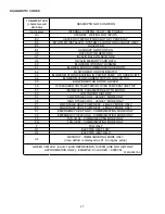
C

OMMUNICATIONS

 T

ROUBLESHOOTING

 C

HART

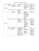
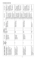
LED LED 

Status 

Indication 

Possible Causes 

Corrective Action(s) 

Notes & Cautions 

Off 

x

 Normal condition 

x

 None 

x

 None 

x

 None 

1 Flash 

x

 Communications 

Failure 

x

 Communications 

Failure 

x

  Depress Learn Button 

x

  Verify that bus BIAS 

and TERM 
dipswitches are in the 
ON position. 

x

 Depress once 

quickly for a power-
up reset 

x

  Depress and hold 

for 2 seconds for 
an out-of-box reset 

Red 

Communications 

LED 

2 Flashes 

x

 Out-of-box reset 

x

  Control power up 

x

 Learn button 

depressed 

x

 None 

x

 None 

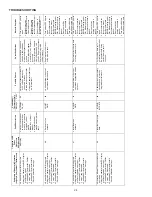
Off 

x

 No power 

x

 Communications 

error 

x

  No power to air 

handler 

x

 Open fuse 

x

 Communications error 

x

  Check fuses and 

circuit breakers; 
replace/reset 

x

  Replace blown fuse 

x

  Check for shorts in 

low voltage wiring in 
air handler/system 

x

  Reset network by 

depressing learn 
button 

x

  Check data 1/ data 2 

voltages 

x

 Turn power OFF 

prior to repair 

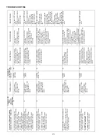
1 Steady 

Flash 

x

  No network found 

x

 Broken/ disconnected 

data wire(s) 

x

  Air handler is installed 

as a non-
communicating/ 
traditional system 

x

 Check 

communications 
wiring (data 1/ data 2 
wires) 

x

 Check wire 

connections at 
terminal block 

x

  Verify air handler 

installation type (non-
communicating/ 
traditional or 
communicating) 

x

  Check data 1/ data 2 

voltages 

x

 Turn power OFF 

prior to repair 

x

 Verify wires at 

terminal blocks are 
securely twisted 
together prior to 
inserting into 
terminal block 

x

  Verify data1 and 

data voltages as 
described above 

Rapid 

Flashing 

x

 Normal network 

traffic 

x

  Control is “talking” on 

network as expected 

x

 None 

x

 None 

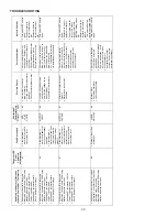
Green Receive 

LED 

On Solid 

x

  Data 1/ Data 2 

miss-wire 

x

  Data 1 and data 2 

wires reversed at air 
handler, thermostat, 
or ComfortNet™ 
compatible outdoor 
AC/HP 

x

  Short between data 1 

and data 2 wires 

x

  Short between data 1 

or data 2 wires and R 
(24VAC) or C (24VAC 
common) 

x

 Check 

communications 
wiring (data 1/ data 2 
wires) 

x

 Check wire 

connections at 
terminal block 

x

  Check data 1/ data 2 

voltages 

x

 Turn power OFF 

prior to repair 

x

 Verify wires at 

terminal blocks are 
securely twisted 
together prior to 
inserting into 
terminal block 

x

  Verify data1 and 

data voltages as 
described above 
Summary of Contents for AVPTC**14 Series

Page 1: ...4 Start Up Procedure 11 15 Regular Maintenance 11 Circulator Blower 13 Troubleshooting 17 ComfortNet System 18 Start Up Procedure 19 Regular Maintenance 20 Troubleshooting 23 Diagnostic Codes 27 Wiring Diagrams 28 RECOGNIZE THIS SYMBOL AS A SAFETY PRECAUTION ATTENTION INSTALLING PERSONNEL Prior to installation thoroughly familiarize yourself with this Installation Manual Observe all safety warning...

Page 2: ...onents are present and intact Report any missing components im mediately to Goodman or to the distributor Use only factory authorized replacement parts see Section 5 Make sure to include the full product model number and serial number when reporting and or obtaining service parts HIGH VOLTAGE Failure to do so may cause property damage personal injury or death Disconnect ALL power before servicing ...

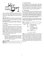
Page 3: ...E Installation of unmatched systems is not permit ted and will void the product warranty 5 3 Interconnecting Tubing Give special consideration to minimize the length of re frigerant tubing when installing air handlers Refer to Re mote Cooling Heat Pump Service Manual RS6200006 and TP 107 Long Line Set Application R 410A for tubing guidelines If possible allow adequate length of tubing such that th...

Page 4: ...ttom left drain connection is for the secondary drain line if used The bottom left drain connection is the primary drain for this application and condensate drain line must be at tached to this drain connection The top connection of the three drain connections on the drain pan must remain plugged for this application The bottom right drain con nection is for the secondary drain line if used Screw ...

Page 5: ...l INTERNAL PART TERMINOLOGY Figure 6 NOTE If removing only the coil access panel from the unit the filter access panel must be removed first Failure to do so may result in panel damage Secondary Drain Port for Upflow Downflow Application Secondary Drain Port for Horizontal Application Blower Access Panel Coil Access Panel Tubing Panel Thumb Screw EXTERNAL PART TERMINOLOGY Figure 7 ...

Page 6: ...ting of the casing On these installations a wrap of 2 fiberglass insulation with a vapor barrier is recommended 7 1 Tubing Size For the correct tubing size follow the specification for the condenser heat pump 7 2 Tubing Preparation All cut ends are to be round burr free and clean Failure to follow this practice increases the chances for refriger ant leaks The suction line is spun closed and requir...

Page 7: ...imum of 1 4 per foot to provide free drainage Provide required support to the drain line to prevent bowing If the secondary drain line is required run the line separately from the primary drain and end it where condensate discharge can be easily seen NOTE Water coming from secondary line means the coil primary drain is plugged and needs immediate attention Insulate drain lines located inside the b...

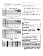
Page 8: ...r using the factory filter rails or externally such as a return air filter grille When using the factory filter rails a nominal 16x20x1 20x20x1 or 24x20x1 actual dimension must be less than 23 x20 fil ter can be installed on a B C and D cabinet respectively the cabinet size is the seventh letter of the model number 11 Electric Heat Refer to the installation manual provided with the electric heat k...

Page 9: ...rical and Control Wiring IMPORTANT All routing of electrical wiring must be made through provided electrical knockouts Do not cut puncture or alter the cabinet for electrical wiring 12 1 Building Electrical Service Inspection This unit is designed for single phase electrical supply only DO NOT OPERATE ON A THREE PHASE POWER SUPPLY Measure the power supply to the unit The supply voltage must be mea...

Page 10: ...rea Attach the Supply wires to the air handler conductors as shown in the unit wiring diagram using appropriatelysizedsolderlessconnectorsorotherNEC or CEC approved means 12 4 2 Air Handler Non Circuit Breaker Heat Kits A terminal block is provided with the HKS kit to attach the power supply and air handler connections Follow the HKS Installation Manual and wiring diagram for com plete wiring deta...

Page 11: ... air handler s integrated control module provides termi nals for Y1 and Y2 and W1 and W2 thermostat con nections This allows the air handler to support the systems shown in the following table Refer to the following figures for typical connections to the integrated control module Ther mostat wiring entrance holes are located in the top of the blower Wire routing must not interfere with circulator ...

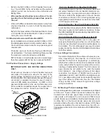
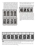
Page 12: ...the air handler NOTE Ground wire may not be present on all dehumidistats 5 To enable the dehumidification function move the de humidification dip switch S7 from OFF to ON See following figure 6 Turn ON power to air handler ON OFF Move to the ON position to enable dehumidification S5 S6 S7 S8 Dip Switches Dehumidification Enable AUXILIARY ALARM SWITCH The control is equipped with two Auxiliary Alar...

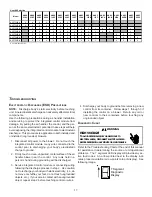
Page 13: ...er If the cooling capacity is in BTU hr divide it by 12 000 to convert capacity to TONs Example Cooling Capacity of 30 000 BTU hr 30 000 12 000 2 5 Tons 2 Determine the proper airflow for the cooling system Most cooling systems are designed to work with airflows between 350 and 450 CFM per ton Most manufactur ers recommend an airflow of about 400 CFM per ton Example 2 5 tons X 400 CFM per ton 1000...

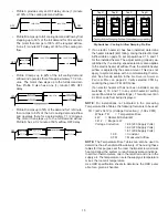
Page 14: ...ction indicates factory setting 75 100 S12 S13 S12 S13 S12 S13 S13 OFF OFF OFF OFF ON ON ON ON Fan Only Selection indicates factory setting 6 The multi speed circulator blower also offers several custom ON OFF ramping profiles These profiles may be used to enhance cooling performance and increase comfort level The ramping profiles are selected using DIP switches 5 and 6 Refer to the following Dip ...

Page 15: ... The adjust setting already es tablished by the cooling speed selection also applies to the electric heater kit airflow Thus the electric heater airflow is adjusted by the same amount This does not apply to systems setup with a communicating thermo stat See Set Up section in the AIR HANDLER ADVANCED FEATURES MENU on page 22 Verify selected CFM by counting the green CFM LED blinks If an electric he...

Page 16: ...ofile see profiles above Set dip switches S5 and S6 to appropriate ON OFF positions Dehumidification To enable set dip switch S7 to ON Cooling airflow will be reduced to 85 of nominal value during cool call when Dehum command is present To disable set S7 to OFF Continuous Fan Speed Use dip switches S12 and S13 to select one of 4 continuous fan speeds Tap A is 25 Tap B is 50 Tap C is 75 Tap D is 10...

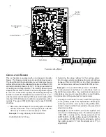
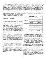
Page 17: ...t touch ungrounded objects etc If you come in contact with an ungrounded object repeat step 2 before touching control or wires 4 Discharge your body to ground before removing a new control from its container Follow steps 1 through 3 if installing the control on a blower Return any old or new controls to their containers before touching any ungrounded object DIAGNOSTIC CHART HIGH VOLTAGE TO AVOID P...

Page 18: ...d features of the ComfortNet sys tem Two way digital communications is accomplished using only two wires The thermostat and subsystem controls are pow ered with 24 VAC Thus a maximum of 4 wires between the equipment and thermostat is all that is required to operate the system AIRFLOW CONSIDERATION Airflow demands are managed differently in a fully commu nicating system than they are in a non commu...

Page 19: ...between Air Handler and Thermostat COMFORTNET SYSTEM ADVANCED FEATURES The ComfortNet system permits access to additional system information advanced set up features and advanced diag nostic troubleshooting features These advanced features are organized into a menu structure See the AIR HANDLER ADVANCED FEATURES MENU section for layout of menu shortcuts DIAGNOSTICS Accessing the air handler s diag...

Page 20: ...ctionable odors flammable vapors or prod ucts of combustion such as carbon monoxide CO which may cause serious personal injury or death REGULAR MAINTENANCE HIGH VOLTAGE Disconnect ALL power before servicing or installing this unit Multiple power sources may be present Failure to do so may cause property damage personal injury or death The only item to be maintained on a regular basis by the user i...

Page 21: ... handler is installed as a non communicating traditional system x Check communications wiring data 1 data 2 wires x Check wire connections at terminal block x Verify air handler installation type non communicating traditional or communicating x Check data 1 data 2 voltages x Turn power OFF prior to repair x Verify wires at terminal blocks are securely twisted together prior to inserting into termi...

Page 22: ...t most recent fault For display only Fault 6 FAULT 6 Least recent fault For display only Clear Fault History CLEAR NO or YES Selecting YES clears the fault history NOTE Consecutively repeated faults are shown a maximum of 3 times DIAGNOSTICS Submenu Item Indication for Display Only not User Modifiable Model Number MOD NUM Displays the air handler model number Serial Number SER NUM Displays the air...

Page 23: ...d in shared data set HTR TOO SMALL EC x Heater kit selected via dipswitches is too small for heater kits in shared data set x Verify electric heat dipswitch settings x Verify the installed electric heater is valid for the air handler blower Check nameplate or Specification Sheet applicable to your model for allowable heater kit s x Verify shared data set is correct for the specific model Re popula...

Page 24: ... Data not yet on network NO NET DATA d0 x Air handler blower does not contain any shared data x Populate shared data set using memory card x Turn power OFF prior to repair x Use memory card for the specific model x Insert memory card BEFORE turning power ON Memory card may be removed after data is loaded x Error code will be cleared once data is loaded x Turn power off before removing memory card ...

Page 25: ...rse power MOTOR MISMATCH b2 x Incorrect circulator blower motor in air handler blower x Incorrect shared data set in integrated control module x Verify circulator blower motor horse power is the same specified for the specific air handler blower model Replace is necessary x Verify shared data set is correct for the specific model Re populate data using correct memory card if required x Turn power ...

Page 26: ... Check power to air handler blower Verify line voltage to blower is within the range specified on the air handler blower rating plate x See Installation Instructions for installation requirements x Turn power OFF prior to repair x Air handler blower fails to operate x Integrated control module LED display provides indicated error code x ComfortNet thermostat Call for Service icon illuminated x Com...

Page 27: ...TRIP OR LOST ROTOR b5 BLOWER MOTOR ROTOR LOCKED b6 OVER UNDER VOLTAGE TRIP OR OVER TEMPERATURE TRIP b7 INCOMPLETE PARAMETER SENT TO MOTOR b9 LOW INDOOR AIRFLOW C1 LOW STAGE COOL LEGACY MODE ONLY C2 HIGH STAGE COOL LEGACY MODE ONLY P1 LOW STAGE HEAT PUMP HEAT LEGACY MODE ONLY P2 HIGH STAGE HEAT PUMP HEAT LEGACY MODE ONLY h1 EMERGENCY HEAT LOW COMMUNICATING MODE ONLY h2 EMERGENCY HEAT HIGH COMMUNICA...

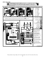
Page 28: ... R2 HTR2 5 M2 W1 1 M4 BK C L1 8 TWO 2 ELEMENT ROWS RD DEHUM TX 3 BL TWO STAGE INTEGRATED CONTROL MODULE TL 3 GND TL NOTE WHEN INSTALLING HEATER KIT ENSURE SPEED TAP DOES NOT EXCEED MINIMUM BLOWER SPEED MBS SPECIFIED FOR THE AIRHANDLER HEATER HTR2 BL R 6 HEAT SEQUENCER R2 RD TRANSFORMER RD FL YL M7 24 V THERMOSTAT CONNECTIONS 2 HEAT SEQUENCER R1 GN 7 WH TR BK RD FL 2 FL L2 BLWR 8 HTR1 BK BK YL EQUI...

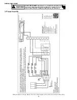
Page 29: ...G MULTIPLE POWER SOURCES MAY BE PRESENT FAILURE TO DO SO MAY CAUSE PROPERTY DAMAGE PERSONAL INJURY OR DEATH WARNING Wiring is subject to change Always refer to the wiring diagram on the unit for the most up to date wiring 3 Phase Heat Kit WIRING DIAGRAMS ...

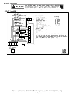
Page 30: ...3 BL PU PU L2 L1 CB4 CB3 CB1 CB2 WH PU TL FL TL FL TL FL TL FL COLOR CODE BK BLACK BL BLUE BR BROWN PK PINK RD RED WH WHITE YL YELLOW WIRING CODE HIGH VOLTAGE LOW VOLTAGE COMPONENT CODE PC 9 PIN CONNECTOR HTR HEATER ELEMENT TL THERMAL LMT RS RELAY SEQUENCER TB TERMINAL BLOCK CB CIRCUIT BREAKER CC CONTACTOR FL FUSE LINK TR TRANSFORMER SR STRAIN RELIEF EM EVAPORATOR MOTOR EBTDR ELEC BLOWER TIME DELA...

Page 31: ...e airflow If cleaning of the outdoor coil becomes necessary hire a qualified servicer Inexperienced people could easily puncture the tubing in the coil Even a small hole in the tubing could eventually cause a large loss of refrigerant Loss of refrigerant can cause poor operation and or severe equipment damage Do not use a condensing unit cover to protect the outdoor unit during the winter unless y...

Page 32: ...facturing Company L P 5151 San Felipe Suite 500 Houston TX 77056 www goodmanmfg com or www amana hac com is a registered trademark of Maytag Corporation or its related entities and is used under license All rights reserved ...

Reviews: