


25
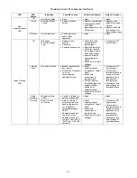
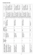
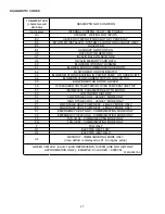
TROUBLESHOOTING
Comfor
tNet™
Ther
mostat Onl
y
S
y
m
p
toms of
A
b
normal Ope
ration
(Legac
y
& Comfor
tNet™ Thermostat)
7-Segment LED
Codes
Characters
Wi
ll
A
lter
nate
Faul
t Desc
ri
pti
on
Messa
ge Code
Possible
Causes
Correct
iv
e A
c
tions
Notes & Cauti
ons
x
Air hand
ler
blow
er fails to
opera
te
.
x
Inte
grated con
trol
module
LED
displa
y
prov
ides
indi
cated error code
.
x
ComfortNe
t™
ther
mosta
t “Call for
Serv
ice” icon il
lumi
nated
.
x
ComfortNe
t™
ther
mosta
t
scroll
s
“Check Air
Handle
r”
message
.
b0
x
Circula
tor
blow
er
motor i
s
no
t ru
nnin
g
w
hen it
should
be
running.
MO
T
O
R
NOT RUN
b0
x
Loose
w
iring co
nne
ctio
n a
t
cir
culator mo
tor
po
w
e
r leads
or circulato
r
mo
tor
pow
er
leads di
scon
nected
.
x
Failed
circulato
r blo
w
er motor.
x
Tighten or corr
ect w
iring
conne
cti
on.
x
Check
circulator
bl
ow
er
motor.
Replace i
f n
e
ce
ssa
ry
.
x
Turn pow
er OFF pri
or to
repair
x
Replace
cir
cula
tor
motor
w
ith corre
c
t
replacemen
t par
t.
x
Air hand
ler
blow
er fails to
opera
te
.
x
Inte
grated con
trol
module
LED
displa
y
prov
ides
indi
cated error code
.
x
ComfortNe
t™
ther
mosta
t “Call for
Serv
ice” icon il
lumi
nated
.
x
ComfortNe
t™
ther
mosta
t
scroll
s
“Check Air
Handle
r”
message
.
b1
x
Inte
grated
con
trol
module ha
s
lost
communication
s w
ith
cir
culator b
low
er
mot
or.
MO
T
O
R
COMM
b1
x
Loose
w
iring co
nne
ctio
n a
t
cir
culator mo
tor
co
ntrol
lead
s.
x
Failed
circulato
r blo
w
er motor.
x
Failed in
tegra
ted
control
module.
x
Tighten or corr
ect w
iring
conne
cti
on.
x
Check
circulator
bl
ow
er
motor.
Replace i
f n
e
ce
ssa
ry
.
x
Check in
tegra
ted
control
module. Repla
c
e
if
nece
ssa
ry
.
x
Turn pow
er OFF pri
or to
repair
x
Replace
cir
cula
tor
motor
w
ith corre
c
t
replacemen
t par
t.
x
Replace
inte
grated
control mod
ule w
ith
corre
ct rep
lacemen
t
part.
x
Air hand
ler
blow
er fails to
opera
te
.
x
Inte
grated con
trol
module
LED
displa
y
prov
ides
indi
cated error code
.
x
ComfortNe
t™
ther
mosta
t “Call for
Serv
ice” icon il
lumi
nated
.
x
ComfortNe
t™
ther
mosta
t
scroll
s
“Check Air
Handle
r”
message
.
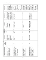
b2
x
Circula
tor
blow
er
motor h
o
rse pow
er
in
shared
da
ta
se
t d
o
e
s
not ma
tch
cir
cula
tor
blow
er motor h
o
rse
pow
er.
MO
T
O
R
M
IS
M
ATCH
b2
x
Inco
rre
ct
circu
lator
blow
er
motor i
n
ai
r han
dler
blow
er.
x
Inco
rre
ct
s
hared
da
ta
se
t in
integra
ted
co
ntro
l
module.
x
Verify
cir
cula
tor
blo
w
er motor
horse
pow
er is
the
same
spe
cifie
d for
the
sp
ecific
air
handler blow
er
model.
Replace
is ne
ce
ssa
ry
.
x
Verify
shar
ed da
ta
set i
s
corre
ct for the
s
pecific
model
.
Re-populate
da
ta
u
s
ing
corre
ct
m
e
m
o
ry
car
d if
required
.
x
Turn pow
er OFF pri
or to
repair
x
Replace
motor
w
ith
corre
ct rep
lacemen
t
part.
x
Use memory
card
for
the spe
ci
fic
model
x
Inse
rt memory
card
BEFORE turning
p
o
w
e
r
ON.
Memory
c
a
rd
may
be remov
ed after
d
a
ta i
s
loaded.
x
Error
code
w
ill be
cleared
on
ce
sha
re
d
data
and mo
tor
hor
se
pow
er match
.
x
Turn pow
er off
befo
re
remov
ing memor
y
c
a
rd
x
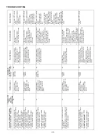
Air hand
ler
blow
er operate
s at redu
ce
d
performan
ce
.
x
Airflow
deliv
ered is
less
than
ex
pected
.
x
Inte
grated con
trol
module
LED
displa
y
prov
ides b3
error
code.
b3
x
Circula
tor
blow
er
motor i
s
opera
ting
i
n
a
pow
er, tempera
ture
, or
speed
limiti
ng
condi
tion
.
MO
T
O
R
LIM
ITS
b3
x
Blocked
fil
ter
s.
x
Restri
ctiv
e
ductw
ork.
x
Undersi
zed
ductw
ork.
x
High
ambien
t
temp
erature
s.
x
Check filte
rs fo
r bl
o
cka
ge.
Clean fi
lter
s or
rem
ov
e
obstruction
.
x
Check du
ctw
ork fo
r blo
ckag
e.
R
e
m
o
v
e
obs
tru
ctio
n.
Veri
fy
all regi
ster
s ar
e
full
y
open.
x
Verify
duc
tw
ork i
s
appropria
tely
si
zed
for
sy
stem
. R
e
si
ze/r
e
p
lace
ductw
ork if ne
ce
ssary
.
x
See "In
s
talla
tion In
str
uction
s"
for installa
tion
requi
rements.
x
Turn pow
er OFF pri
or to
repair.
x
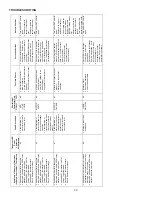
Air hand
ler
blow
er fails to
opera
te
.
x
Inte
grated con
trol
module
LED
displa
y
prov
ides
indi
cated error code
.
x
ComfortNe
t™
ther
mosta
t “Call for
Serv
ice” icon il
lumi
nated
.
x
ComfortNe
t™
ther
mosta
t
scroll
s
“Check Air
Handle
r”
message
.
b4
x
Circula
tor
blow
er
mo
to
r
s
e
ns
es
a l
o
ss
rotor
co
ntro
l.
x
Circula
tor
blow
er
m
o
to
r s
e
ns
es
hi
g
h
curren
t.
MO
T
O
R
TRIPS
b4
x
Abnormal mo
tor
loa
ding,
sudden
change
in speed
or
torque
,
sudd
en bl
o
cka
ge o
f air
handler blow
er/coil
air
inle
t
or
outle
t.
x
High
loading
condi
ti
ons,
blocked
fil
ter
s, v
e
ry re
stri
ctiv
e
ductw
ork, b
lockage
of air
handler blow
er/coil
air
inle
t
or
outle
t.
x
Chec
k
filt
ers,
f
ilt
er
grills/regi
sters, du
ct sy
stem
,
and air
handl
er bl
o
w
er/coil air
inlet/outl
et fo
r bl
ockages.
x
Turn pow
er OFF pri
or to
repair.


