


19
Altitude
High
Fire
Low
Fire
High
Fire
Low
Fire
High
Fire
Low
Fire
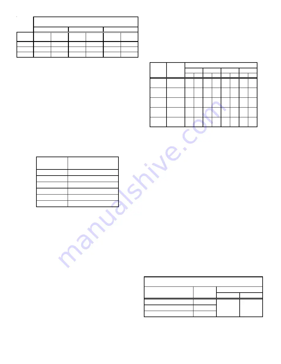
5,000
57,000
42,000
74,000
54,000
92,000
66,500
7,500
53,000
39,000
72,000
53,000
88,000
64,500
10,000
52,000
37,500
71,000
49,000
84,000
60,500
Firing rates may be lower than listed in table.
115,000 kBtu/hr input models require pressure switch change above 7,500'.
Use switch B1370209.
Model (Kbtu/hr)
Maximum Firing Rates at Altitude
70
90
115
It is important to check and adjust the input rate of the furnace to
prevent an overfiring situation. Overfiring can cause premature
heat exchanger failure. The input is controlled by the supply
pressure, orifice size, manifold pressure and heating (calorific)
value of the gas.
The supply pressure must be measured with this and all other
gas burning appliances in operation. The supply pressure must
be adjusted to the pressure range stated on the series and rating
plate. Applications for altitudes in excess of 4,500 feet may require
an orifice change. Alternately standard de-rate for altitude from
National Fuel Gas Code ANSI Z223.1 of 4% per 1000’ may be
taken. Refer to the most recent version of ANSI Z223.1 for correct
gase orifice. The orifices must be selected using the table below.
The furnace derate is 4% for each 1,000 feet above sea level. This
table is based upon a heating value of approximately 1,000 Btu/ft
3
NAT. GAS
ORIFICE SIZE
0 - 2,000
#43
3,000
#44
4,000
#44
5,000
#45
6,000
#45
7,000
#46
ALTITUDE
The input to the furnace must be checked AFTER reorificing.
For altitudes above 7,000 feet, refer to appropriate section of the
National Fuel Gas Code, ANSI Z223.1. To calculate the input of the
furnace for installations in altitudes over 2,000 - 7,000 feet, use
the following formula:
Corrected Input = Series & Rating Plate Input - (Altitude X .04) X
(Series & Rating Plate Input / 1000)
Example:
Corrected input for a 90,000 Btu/hr. appliance installed at an
altitude of 6,000 ft. utilizing natural gas with a heating value of
1,000 Btu/ft
3
is determined by-
Corrected Input = 90,000 - (6,000 X .04) X (90,000 / 1,000)
Corrected Input = 90,000 - (240 X 90)
Corrected Input = 90,000 - 21,600
Corrected Input = 68,400
Using the orifices sized as shown in the table for 6,000 feet (#45),
a meter time of 52.6 seconds is measured. The actual firing rate
of the furnace is:
Input = 1,000 (heating value of the gas) X 3600 (constant) / 52.6
(meter time for 1 ft
3
of gas)
Input = 3,600,000 / 52.6
Input = 68,400 Btu/h
M
ETER
T
IME
I
N
M
INUTES
AND
S
ECONDS
F
OR
N
ORMAL
I
NPUT
R
ATING
OF
F
URNACES
E
QUIPPED
F
OR
U
SE
W
ITH
N
ATURAL
G
AS
A
T
0 - 2,000 F
EET
A
LTITUDE
Min. Sec. Min. Sec. Min. Sec. Min. Sec.
1
1
21
1
30
1
33
1
39
10
13
30
15
00
15
36
16
30
1
0
54
1
00
1
03
1
06
10
9
0
10
10
10
24
11
00
1
0
41
0
45
0
47
0
50
10
6
45
7
30
7
48
8
15
1
0
32
0
36
0
37
0
40
10
5
24
6
00
6
14
6
36
1
0
27
0
30
0
31
0
33
10
4
30
5
00
5
12
5
30
Meter Size
ft
3
Input
Btu/hr
900
1,000
1040
1,100
Heat Value
120,000
40,000
60,000
80,000
100,000
In Canada, the series and rating plate input for the furnace apply
to installations up to 2,000 feet (610m) above sea level. Kit
HA-02
for natural and LP gases is required to convert furnaces from
elevations of 2,000 to 4,500 feet (610m to 1,370m). Canadian
certification applies to the installations of up to 4,500 feet above
sea level. Installations above 4,500 feet are subject to acceptance
by the local authorities having jurisdiction.
Do
not
derate the furnace by adjusting the manifold pressure to a
lower pressure than specified on the furnace rating plate. The
combination of the lower air density and a lower manifold pressure
will prohibit the burner orifice from drawing the proper amount of
air into the burner. This may cause incomplete combustion,
flashback, and possible yellow tipping.
In some areas the gas supplier may artificially derate the gas in
an effort to compensate for the effects of altitude. If the gas is
artificially derated, the appropriate orifice size must be determined
based upon the BTU/ft
3
content of the derated gas and the altitude.
Refer to the National Fuel Gas Code, NFPA 54/ANSI Z223.1, and
information provided by the gas supplier to determine the proper
orifice size.
Some models require a pressure switch change due to the reduced
air density above certain altitudes. Refer to the following table to
determine proper pressure switch settings for your application.
A different pressure switch may be required at high altitude
regardless of the Btu/ft
3
content of the fuel used. Contact your
distributor for appropriate altitude ranges and pressure switch
kits.
High
Low
70
NR
90
NR
115
7,500
Pressure Switch Changes
0.5" w.c.
0.3" w.c.
Setting
Furnace Input (kBtu/hr)
Altitude(ft)