I
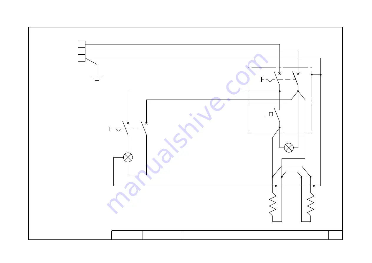
74800040 Revisione 01 MOD. AMALFI L - P120E L 208/240VAC, 1ph
1/1
LC
ILC
240VAC, 1ph
7
PE
N
L
6
13
9
21
20
11
10
RX
18
15
14
19
17
12
16
STC
TC
8
ITC
1
3
4
5
208VAC, 1ph
Page 1: ...P120E AMALFI Instructions manual Manuel d instructions Electric oven Four electrique Serial numbers Cod 73340800 Ver A3...
Page 2: ...ration of the oven DEAR CUSTOMER Before using the oven please read this user manual Oven safety devices should always be maintained in a proper state of efficiency to ensure the operator s safety This...
Page 3: ...rules The appliances must be installed in conformity with current national regulations Remove the protective film from the outside of the oven pulling it gently to remove all the adhesive Should any a...
Page 4: ...in particular the glass become hot so that care must be taken not to touch them so as to prevent scalding When opening the door make sure you stand at a safe distance from any hot steam that may come...
Page 5: ...ulator buttons the economy function will once again adjust the values automatically until the sum is once again equal to or less than 9 When the manual economy function is disabled the values displaye...
Page 6: ...UP THE ELECTRONIC CONTROL UNIT WITH TIMER The electronic control panel is fitted with an additional button fig 17 15 Timer button The control unit enables 3 baking timers to be set countdown as well...
Page 7: ...to ensure that the oven remains in a good state and failure to observe them may result in serious damage which will not be covered by the warranty The chamber is suitable only for cooking bread and p...
Page 8: ...RED GLASS After carrying out the operations described in 5 1 above to replace the tempered glass proceed as follows Remove the front fixing screws Take off the front panel Take off the front gasket Re...
Page 9: ...crews plate C Disconnect the faston connectors for the indicator and or the light switch Replace the indicator light item 14 plate C Replace the push button item 4 plate C Perform the above operations...
Page 10: ...itale pour le fonctionnement correct et durable du four CHER CLIENT Avant d utiliser de ce four veuillez lire le pr sent manuel Pour la s curit de l op rateur les dispositifs du four doivent constamme...
Page 11: ...ricit R glements de b timent et contre les incendies des locaux Prescriptions en vigueur contre les accidents D terminations en vigueur des normes lectrotechniques L installation des appareils doit tr...
Page 12: ...Fig 10 11 14 avec le symbole auquel doit tre correctement reli le fil de terre En outre ces appareillages doivent tre compris dans le circuit du syst me quipotentiel la borne pr vue telle raison se tr...
Page 13: ...entre en fonction automatiquement et une led rouge s allume en continu sur l angle sup rieur droit de la touche fig 17 d tail 10 Cela signifie que les r sistances ciel et sole ne sont jamais aliment...
Page 14: ...dure 3 secondes o En maintenant appuy e la touche 17a d tail 13 pendant 3 secondes le boiler s teint 3 3 2 MISE EN MARCHE DE LA CHAMBRE DE CUISSON AVEC ECHAPPEMENT DES VAPEURS MODE PROGRAMS Toutes les...
Page 15: ...d appuyer sur la touche Marche Arr t fig 17 d tail 9 en m me temps que la touche Timer fig 17 d tail 8 3 7 CHOIX ENTRE DEGR S CENTIGRADES ET DEGR S FAHRENHEIT Appuyer simultan ment sur les touches li...
Page 16: ...REMPLACEMENT DU TRANSFORMATEUR Les op rations du point 5 1 ex cut es pour remplacer le transformateur proc der comme suit Enlever le panneau lat ral d tail 29 tab A d tail 22 tab B en d vissant les qu...
Page 17: ...tion d tail 6 tab C Remplacer l embout et ou la poign e 5 4 6 REMPLACEMENT DE LA LED LUMINEUSE ET OU DE L INTERRUPTEUR LUMIERE Les op rations du point 5 1 ex cut es pour remplacer la led lumineuse et...
Page 18: ...40 5 32 102 51 31 32 132 51 31 32 132 59 27 32 152 Z inch cm 3 15 16 10 3 15 16 10 3 15 16 10 3 15 16 10 Y inch cm 50 25 32 129 38 31 32 99 50 25 32 129 53 15 16 137 W inch cm 5 1 8 13 5 1 8 13 5 1 8...
Page 19: ...66 5 32 148 lb kg 265 120 330 150 485 220 P120E B A B C X inch cm 63 3 8 161 63 3 8 161 63 3 8 161 Z inch cm 3 15 16 10 3 15 16 10 3 15 16 10 Y inch cm 37 13 32 95 45 9 32 115 61 1 32 155 W inch cm 5...
Page 20: ...nection cable model H07RN F C ble de connection type H07RN F 4x9 AWG 4x7 AWG 3x14 AWG V with 1740 Watts steamer avec le cuiseur vapeur 1740 Watts W with 3480 Watts steamer avec le cuiseur vapeur 3480...
Page 21: ......
Page 22: ...208 VAC 1ph 60Hz 240 VAC 1ph 60Hz 208 VAC 3ph 60Hz 240 VAC 3ph 60Hz L1L2 L3 GND L2 L1 L3 GND L L1...
Page 23: ...Fig 18...
Page 24: ......
Page 25: ...A...
Page 26: ...Thermocouple And Clamp Thermocouple Et Borne 47 Heating Element R sistance 48 Heating Element R sistance 49 Suppressor Suppresseur 50 Terminals Board Platine Des Bornes 53 Remote Control Switch T l r...
Page 27: ...B...
Page 28: ...8 Door Porte 30 Ball Knob Pommeau 31 Cover Calotte 32 Bulb Ampoule 33 Safety Thermostat Thermostat De S curit 34 Terminal Borne 35 Terminal Borne 36 Switch Interrupteur 43 Transformer Transformateur 4...
Page 29: ...C...
Page 30: ...oign e 6 Ring nut Embout 7 Thermostat Thermostat 8 Bulb Ampoule 9 Lamp holder Douille 10 Heating element R sistance 14 Indicator light Led lumineuse 15 Magnetized pawl Cliquet aimant 16 Cover Calotte...
Page 31: ...D...
Page 32: ...noid valve lectrovanne 4 Contactor Contacteur 5 Suppressor Suppresseur 6 Thermostat Thermostat 7 Water inlet tube Tuyau d arriv e d eau 8 Stainless hose Tuyau en acier inoxydable 9 Ball valve Robinet...
Page 33: ...20 14 TSS TC A2 A2 A1 16 A1 15 19 18 17 A2 A1 TP 21 23 22 24 25 26 6 4 2 5 1 3 TC 6 A2 4 2 5 3 1 A1 32 30 31 34 33 35 XP PE 2 L1 L2 240VAC 3Ph 60Hz L3 20 8 3 1 7 2 SE 44 46 1 9 12 11 10 19 7 18 2 48...
Page 34: ...le TC Ceiling contactor Contacteur ciel TP Floor contactor Contacteur sole SE Pyrometer Pyrom tre TCP Thermocouple Thermocouple TR Transformer Transformateur IG Main switch Interrupteur alimentation T...
Page 35: ...2 208Vac 3ph 60Hz KM2 KM2 C1 C2 23 22 3 2 1 25 60 6 4 8 7 5 9 5 1 3 6 2 4 14 5 1 3 6 2 4 33 30 36 42 39 45 12V COM RES CIELO RES PLATEA LUCE N U ALLARM N U ALLARM 25 R1 R2 R3 R4 R5 R6 R7 R8 R9 R10 R11...
Page 36: ...ling contactor Contacteur ciel KM1 Floor contactor Contacteur sole SE Pyrometer Pyrom tre TC Thermocouple Thermocouple TR Transformer Transformateur QS Main switch Interrupteur alimentation TS Safety...
Page 37: ...47 5 3 1 A1 26 6 25 24 4 2 TC TSS 9 50 52 18 51 TP TC A1 A2 A1 A2 54 53 HLD 56 57 3 TR 4 18 2 3 5 6 16 1 15 12 54 19 53 10 9 11 7 8 1 2 4 3 21 20 SE TCP 55 13 12 14 10 IG 7 8 4 22 23 11 19 1 208 240VA...
Page 38: ...m contactor Contacteur plan de cuisson SE Pyrometer Pyrom tre TCP Thermocouple Thermocouple TR Transformer Transformateur IG Switch Interrupteur TSS Safety thermostat Thermostat de securit HLD S Light...
Page 39: ...25 6 43 5 39 3 1 A1 A2 47 26 4 2 24 25 6 TC RXC L1 PE L2 L3 2 1 208 240VAC 3ph 60Hz TSS 9 50 52 18 51 TP TC A1 A2 A1 A 2 54 53 HLD 56 57 3 TR 4 18 2 3 5 6 16 1 15 12 54 19 53 10 9 11 7 8 1 2 4 3 21 2...
Page 40: ...sole SE Pyrometer Pyrom tre TCP Thermocouple Thermocouple TR Transformer Transformateur IG Main switch Interrupteur alimentation TSS Safety thermostat Thermostat de s curit HLD S Internal lamp Lampe...
Page 41: ...I 74800040 Revisione 01 MOD AMALFI L P120E L 208 240VAC 1ph 1 1 LC ILC 240VAC 1ph 7 PE N L 6 13 9 21 20 11 10 RX 18 15 14 19 17 12 16 STC TC 8 ITC 7 6 1 3 4 5 208VAC 1ph...
Page 42: ...h Interrupteur lumi re chambre ITC Thermostat switch Interrupteur thermostat TC Thermostat Thermostat STC Thermostat light Led du thermostat LC Light Lumi re RX Heating elements R sistances 74800040 A...