background image

A


1035 22nd Avenue, Unit 1


n


Oakland, CA 94606                


P


510.489.2530


E


[email protected]


W


alwusa.com

INSTALLATION INSTRUCTIONS

LIGHTPLANE 2

LP2SMB/W  |  Surface and Wall Mount |  LED

Summary of Contents for LIGHTPLANE 2

Page 1: ...A 1035 22nd Avenue Unit 1 n Oakland CA 94606 P 510 489 2530 E TalkToUs alwusa com W alwusa com INSTALLATION INSTRUCTIONS LIGHTPLANE 2 LP2SMB W Surface and Wall Mount LED...

Page 2: ...nuous row mounting 1 Lisez toutes les instructions 2 Installez conform ment la r glementation du code lectrique national et local 3 Ce produit est destin tre install et entretenu par un lectricien agr...

Page 3: ...818 A 0 Table of Contents Troubleshooting 11 Wiring Diagrams 12 Installation 5 Prepare Ceiling 5 Connecting Multiple Sections 10 SMB Surface Back Mount 5 Wall Mount 7 Luminaire Overview 4 Diagrams 4 C...

Page 4: ...4 120 F 20 50 C Environment Dry and damp locations Quick Specs Junction Box Optional Parts by others Wood Screws 10 1 5 long Conduit NM non metallic cable or similar if not using J Box OPTIONAL HARDW...

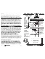
Page 5: ...se run conduit NM cable to powerfeed location 2 Install Canopy J Box Wiring S A M P L E D R A W I N G Carefully remove lens using suction cup or similar 3 Remove Lens Remove heatsink reflector screws...

Page 6: ...le Sections If Necessary Please see steps 28 through 33 for directions on connecting multiple sections 8 Raise Fixture to Ceiling Connect Wiring Raise entire fixture to ceiling and connect wiring insi...

Page 7: ...Mount Carefully remove lens using suction cup or similar 15 Remove Lens WALL ELECTRICAL WIRING A T MUST 1 120V MED 3000K MED 3000K 0 10V 10 EXT R AL 120V NA Follow steps 1 2 to prepare ceiling Instal...

Page 8: ...ns If Necessary Please see steps 27 through 32 for directions on connecting multiple sections 20 Raise Fixture to Wall Connect Wiring Raise entire fixture to wall and connect wiring inside fixture Ref...

Page 9: ...6 Turn Power On Re install each heatsink reflector section CAUTION Do not pinch wires while reattaching 22 Re install Heatsink Reflector Re install heatsink reflector screws to attach back to housing...

Page 10: ...and that there are no gaps between sections 31 Tighten Joiner Screws on Inner Corner Installation Connecting Multiple Sections Tighten joiner set screws as shown using a 5 64 hex key for the sides and...

Page 11: ...stomer support Only a certified electrician can service and troubleshoot product field issues Always turn main power off before servicing fixture Fixture section s do not illuminate Possible loose low...

Page 12: ...60Hz DIM DIM 0 10V Dimming Black White Green Clear Black DMX in shield DMX in Line Voltage Hot Line Voltage Neutral Ground L N AC 50 60Hz DMX In Shield DMX in Red DMX in DMX in Clear Black DMX out sh...

Reviews: