13
4.4 Rack Mounting
5. Preset Functions Descriptions
5.1 Reverbs
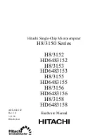
Impulse Response
Late Reflections
Reflections
Early
time
5. Depending on the input sensitivity of the mixer's channels or Aux Returns,
the [OUTPUT] knob of the
Verb should be set somewhere between "2:00"
and fully clockwise ("5:00").
6. Turn up the AUX RETURN level until desired level of effect in the mix is re-
ached. The control in the chain that may need to be set to a low level is the
Aux Return on the mixer itself. Here is where should increase or decrease
the overall effect level in the mix to minimize the noise.
The most secure mounting is on an "universal" rack shelf, available from various
rack manufacturers or music dealer. Up to two
Verb's may be mounted side-by-
side in a standard universal EIA 19" equipment rack.
Reverb in nature, is the sum of a large number of distinct echoes generated by the
reflection of the original sound against obstacles (i.e. walls). In a real acoustic space,
the amplitude and brightness of these reflections decay over time and the decaying
is depending on the room size, the position of the sound source acoustic space, the
"nature" of obstacles (shape, material, dimension, etc.), and many other factors.
This algorithm is the simulation of a large acoustic space (as a concert hall).
Halls want to simulate large rooms with many reflective surfaces, where sounds
can be reflected and also hided, changing its "colour" over time. This is a classic
reverb and can be used with all sound sources as vocals, drums or acoustic and
electric instruments.
- This is a large bright hall program with 54ms predelay, and can be used
Hall 1
for almost anything.
a. Halls
R
LTO
Hall 3
Plate 1
Plate 2
Room 2
Room 1
Room 3
Hall 2
Hall 1
OUTPUT
INPUT
MIX
VARIATIONS
0
10
0
10
0
10
SIGNAL
1
2
3
4
5
6
7
8
9
10
11
12
13
14
15
16
POWER
Flange
Chorus
Tremolo
Delay/Rev
Delay
Chorus/Rev
Flange/Rev
Rotary
Verb
TM
24 32 BIT DIGITAL EFFECTS MODULE
ON OFF
R
LTO
Hall 3
Plate 1
Plate 2
Room 2
Room 1
Room 3
Hall 2
Hall 1
OUTPUT
INPUT
MIX
VARIATIONS
0
10
0
10
0
10
SIGNAL
1
2
3
4
5
6
7
8
9
10
11
12
13
14
15
16
POWER
Flange
Chorus
Tremolo
Delay/Rev
Delay
Chorus/Rev
Flange/Rev
Rotary
Verb
TM
24 32 BIT DIGITAL EFFECTS MODULE
ON OFF