background image

MN-29758 (Rev. 6) 05/15 •


TH/III-SK/III Series Cook, Hold, Smoke •

 25

eQUIpMent care

Under normal circumstances, this 

oven should provide you with long 

and trouble free service.  There is no 

preventative maintenance required, 

however, the following Equipment Care Guide 

will maximize the potential life and trouble free 

operation of this oven.
The cleanliness and appearance of this equipment 

will contribute considerably to operating efficiency 

and savory, appetizing food.  Good equipment that 

is kept clean works better and lasts longer.

clean daIly

1.  Disconnect unit from power 

source, and let cool.

2.  Remove all detachable items 

such as wire shelves, side 

racks, and drip pans.  Clean 


these items separately.

3.  Wipe the interior metal surfaces 


of the oven with a paper towel to 

remove loose food debris.

4.  Clean the interior metal surfaces of the cabinet 

with a damp clean cloth or sponge and any good 

commercial detergent.  

note:

    Avoid the use of abrasive cleaning 

compounds, chloride based cleaners, or 

cleaners containing quaternary salts.  Never 

use hydrochloric acid (muriatic acid) on 

stainless steel.

5.   Spray heavily soiled areas with a water soluble 

degreaser and let stand for 10 minutes, then 

remove soil with a plastic scouring pad.

6.   Wipe control panel, door vents, door handles, 

and door gaskets thoroughly since these areas 

harbor food debris.

7.  Rinse surfaces by wiping with sponge and clean 


warm water.

8.   Remove excess water with sponge and wipe dry 

with a clean cloth or air dry.  Leave doors open 

until interior is completely dry.  Replace side 

racks and shelves.

9.  Wipe door gaskets and control panel dry with a 

clean, soft cloth.

10. Interior can be wiped with a sanitizing solution 


after cleaning and rinsing.  This solution must 


be approved for use on stainless steel food 


contact surfaces.

11.   To help maintain the protective film coating 

on polished stainless steel, clean the exterior 

of the cabinet with a cleaner recommended 

for stainless steel surfaces.  Spray the cleaning 

agent on a clean cloth and wipe with the grain 

of the stainless steel.

12.  Clean any glass with a window cleaner.
Always follow appropriate state or local health 

(hygiene) regulations regarding all applicable 

cleaning and sanitation requirements for equipment.

c a r e   a n d   c l e a n I n g

    d a n g e r

Disconnect unit from power source 
before cleaning or servicing. Failure 
to observe this precaution can cause 
electrical shock and personal injury.

d a n g e r

At no time should the interior or 
exterior be steam cleaned, hosed 
down, or flooded with water or 
liquid solution of any kind. Do not 
use water jet to clean.
Severe damage or electrical 
hazard could result. Failure to 
observe this precaution will void 
the warranty.

Summary of Contents for 1000-SK/III

Page 1: ... A CANADA FAX 262 251 7067 800 329 8744 U S A ONLY www alto shaam com Consult instructions for operation and use Cook Hold Smoke Oven Deluxe Control Model 300 TH III 500 TH III 750 TH III 1000 TH III 1200 TH III 767 SK III 1767 SK III 1000 SK III 1200 SK III InstallatIon operatIon MaIntenance 1200 TH III 1767 SK III 750 TH III 300 TH III 1000 SK III 500 TH III ...

Page 2: ...18 19 Smoking Instructions 20 User Options 21 HACCP 22 General Holding Guidelines 23 Care and Cleaning Protecting Stainless Steel Surfaces 24 Cleaning Agents 24 Cleaning Materials 24 Equipment Care 25 Clean Daily 25 Clean the Door Vents 26 Check Overall Condition of Oven 26 Daily Prong Cleaning 26 Sanitation Sanitation Food Safety 27 Internal Food Product Temperatures 27 Service Trouble Shooting E...

Page 3: ... or maintenance note All claims for warranty must include the full model number and serial number of the unit UnpacKIng Carefully remove the appliance from the carton or crate note Do not discard the carton and other packaging material until you have inspected the unit for hidden damage and tested it for proper operation Read all instructions in this manual carefully before initiating the installa...

Page 4: ...f accident or damage to the unit Operators must also receive regular safety instructions Any troubleshooting guides component views and parts lists included in this manual are for general reference only and are intended for use by qualified and trained technicians This manual should be considered a permanent part of this appliance This manual and all supplied instructions diagrams schematics parts...

Page 5: ...allation and or outside venting should not be a requirement in most areas Verify local codes for locations where more restrictive codes are applicable danger Improper installation alteration adjustment service cleaning or maintenance could result in property damage severe injury or death Read the installation operating and maintenance instructions thoroughly before installing servicing or operatin...

Page 6: ...5 QUARTS 28 5 LITERS prodUct pan capacIty 500 TH III 40 lb 18 kg MAXIMUM voluMe MaxiMuM 30 quarts 38 liters weIght 500 th III NET 140 lb 64 kg SHIP 180 lb 82 kg 21 532mm Shown with optional bumper 29 7 8 758mm 41 1 16 1043mm Electrical Connection 44 1 16 1118mm 58 1 4 1479mm 14 1 2 368mm 30 3 16 767mm 21 7 8 556mm 16 406mm 33 3 8 848mm 5 1 8 130mm 18 1 16 458mm Pass Through Option Pass Through Opt...

Page 7: ... 26 5 8 676mm 30 3 16 767mm 24 1 8 612mm 17 432mm Elec Connection 34 864mm 31 5 8 802mm 28 9 16 726mm 79 2006mm 34 7 8 886mm 32 1 2 826mm with optional 2 1 2 casters 35 1 4 894mm with optional 5 casters 33 3 4 857mm with optional 6 legs 26 3 4 679mm Cord Length 120V 5 ft 1524mm 208 240V 5 ft 1524mm 230V 8 ft 2438mm 26 5 8 676mm 25 11 16 651mm 31 11 16 804mm with optional 2 1 2 casters 35 1 16 890m...

Page 8: ...Cord Length 208 240V 5 ft 1524mm 230V 8 ft 2438mm 22 1 2 572mm Shown with optional bumper Pass Through Option 22 1 2 572mm 5 1 8 130mm 40 3 16 1021mm with 3 1 2 89mm casters 38 5 8 981mm with optional 2 1 2 casters 42 1067mm with optional 5 casters 41 7 8 1063mm with optional 6 legs 20 1 2 521mm 23 1 2 597mm 51 1294mm 34 1 2 876mm 25 1 16 636mm 26 7 8 683mm 37 940mm 31 5 8 802mm Cord Length 230V 8...

Page 9: ... 1877mm with optional 3 1 2 casters 74 11 16 1897mm with optional 6 legs 23 5 8 600mm 22 1 2 572mm 22 1 2 572mm 20 1 2 521mm 23 15 16 608mm 75 5 8 1920mm with 5 127mm casters 6 13 16 172mm 73 7 8 1877mm with optional 3 1 2 casters 74 11 16 1897mm with optional 6 legs 25 1 16 636mm 34 1 2 876mm 51 1294mm 72 1 4 1835mm 31 5 8 802mm 32 1 4 819mm 24 1 4 613mm Shown with optional bumper Electrical Conn...

Page 10: ...4 1441mm 54 1 16 1373mm 11 5 8 295mm 31 3 4 807mm 24 1 8 613mm 58 9 16 1487mm Electrical Connection 61 15 16 1572mm with 5 127mm casters 6 13 16 172mm 60 11 16 1540mm with optional 3 1 2 89mm casters 62 1 8 1577mm with optional 6 152mm legs 32 3 4 832mm prodUct pan capacIty PER COMPARTMENT 100 lb 45 kg MAXIMUM VOLUME MAXIMUM 53 QUARTS 67 LITERS weIght MODEL NET WEIGHT SHIP WEIGHT 1767 SK III 359 l...

Page 11: ...ck 20 lb 9 kg Apple Cherry Hickory Maple WC 22543 WC 22541 WC 2829 WC 22545 WC 22543 WC 22541 WC 2829 WC 22545 WC 22543 WC 22541 WC 2829 WC 22545 WC 22543 WC 22541 WC 2829 WC 22545 optIons an d accessorIes 300 TH III 500 TH III 750 TH III 1000 TH III 1200 TH III Bumper Full Perimeter Not available with 2 1 2 casters 5011161 5010371 5009767 5009767 Carving Holder PRIME RIB STEAMSHIP CAFETERIA ROUND...

Page 12: ... to locate set screw hole Drill with 30 Bit and Tap 8 32 note The flange on the stacking posts must face the outside of the unit 3 remove the four top mounting screws from the lower unit place the upper appliance which has the stacking posts installed on top of the bottom unit center the top unit from front to back re install the four screws through the flange of the four stacking posts A DETAIL A S...

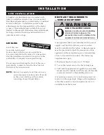
Page 13: ...properly level this oven can cause improper function and will result in the uneven baking with products consisting of semi liquid batter restraInt reQUIreMents MoBIle eQUIpMent Any appliance that is not furnished with a power supply cord but that includes a set of casters must be installed with a tether Adequate means must be provided to limit the movement of this appliance without depending on or...

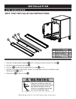
Page 14: ...ded tape 1 which is attached to the back of drip tray holder 2 2 Remove backing on double sided tape 1 3 Put screws 3 through holes and attach drip tray holder 2 to unit 4 Optional but strongly recommended apply a line of food grade silicone caulk along top edge of drip tray holder 2 to seal 5 Place drip tray 4 in drip tray holder 2 Item Description Qty 1 Double Sided Tape 1 2 Drip Tray Holder 1 3...

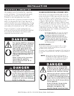
Page 15: ...adequately grounded in accordance with local electrical codes or in the absence of local codes with the current edition of the National Electrical Code ANSI NFPA No 70 In Canada all electrical connections are to be made in accordance with CSA C22 1 Canadian Electrical Code Part 1 or local codes Failure to observe this precaution may damage the appliance result in electrical shock fire or personal ...

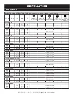
Page 16: ... 0 2 9 3 9 CORD NO PLUG 230V 1 50 60 12 2 2 8 1000 TH III 208V 240V 1 60 14 0 16 0 2 9 3 9 CORD NO PLUG 230V 1 50 60 12 2 2 8 1200 TH III 208V 240V 1 60 29 0 33 3 6 1 8 0 NO CORD OR PLUG 230V 1 50 60 28 7 6 6 NO CORD OR PLUG 380 415V 3 50 60 16 5 6 0 NO CORD OR PLUG 1200 TH III U K ONLY 230V 1 50 60 21 5 4 9 NO CORD OR PLUG 767 SK III 208V 240V 1 60 16 0 18 5 3 9 4 4 CORD NO PLUG 230V 1 50 60 14 0...

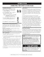
Page 17: ...down arrows to set the cooking time to approximately 2 hours Allow the oven to cycle for approximately 2 hours or until no odor is detected caUtIon Metal parts of this equipment become extremely hot when in operation To avoid burns always use hand protection when operating this appliance danger At no time should the interior or exterior be steam cleaned hosed down or flooded with water or liquid s...

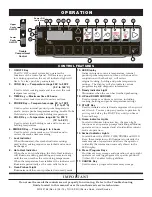
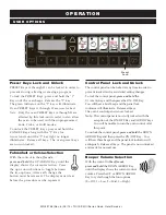
Page 18: ...erior oven air temperature internal product probe temperature time or when used in conjunction with other keys will review original cooking holding and probe temperature settings The display will also indicate various programming and diagnostic information 11 Ready Indicator Light Illuminates when the oven has finished preheating 12 UP and DOWN ARROWS Used to increase or decrease set time includin...

Page 19: ...BE and HOLD keys will alternate signaling the Probe Hold mode Press the UP or DOWN ARROW Keys to set probe holding temperature Set Smoke time if desired hot smoke Press SMOKE Key Press the UP or DOWN ARROW Keys to set the smoke time desired The last set time will be displayed To save program to a preset Select desired PRESET key A H for the product programmed by the previous steps Press and hold t...

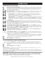
Page 20: ... The cook tiMe probe and HOLD keys include an amber indicator light to identify the information being displayed Power Fail Detect If the power were to fail for any reason while heating the control will retain in memory the programmed operating conditions When power is restored the control will resume operating from the point where it was interrupted and the ON OFF indicator light will flash indica...

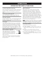
Page 21: ...ure inside the oven To use the probe for cooking remove it from the bracket and wipe the full length of the metal probe with a disposable alcohol pad to clean and sanitize before using Only the tip of the probe senses the internal product temperature therefore it is important the tip be placed correctly in the product for internal temperature accuracy Push the probe tip halfway into the product po...

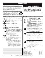
Page 22: ... period of 3 seconds To Set Cold Smoke Holding Temperature The temperature will default to the last smoke holding temperature set by the user The holding temperature range is 14 F to 205 F 10 C to 96 C To increase this default temperature press the HOLD Key and press the UP ARROW to set a higher default temperature to set smoking Verification Temperature IF DESIRED Press the PROBE Key Press the UP...

Page 23: ...options After each change the button must be released The display must clear before the procedure can be repeated control panel lock and Unlock The control panel can be locked at any time in order to prevent inadvertent or accidental setting changes To lock the control panel press and hold the UP ARROW Key and then press the ON OFF Key You will hear a brief beep and the panel lock indicator will i...

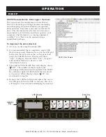
Page 24: ...ed OFF 2 It is recommended that a completely empty USB flash drive is used Remove the cap of the USB port located on the right side of the control panel and insert the USB flash drive Display will show Usb If display does not show Usb try again with another flash drive device or call Alto Shaam Service 3 Press and hold the START Key until display shows XYZ The number at the far right is the percen...

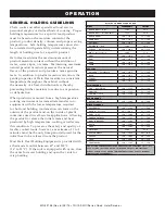
Page 25: ...e safety and quality of freshly cooked foods however a maximum of 1 to 2 minutes must be the only time period allowed for the initial heat to be released from the product Most Halo Heat Holding Equipment is provided with a thermostat control between 60 and 200 F 16 to 93 C If the unit is equipped with vents close the vents for moist holding and open the vents for crisp holding h o l d I n g t e M ...

Page 26: ...leanIng agents Use non abrasive cleaning products designed for use on stainless steel surfaces Cleaning agents must be chloride free compounds and must not contain quaternary salts Never use hydrochloric acid muriatic acid on stainless steel surfaces Always use the proper cleaning agent at the manufacturer s recommended strength Contact your local cleaning supplier for product recommendations clea...

Page 27: ...l panel door vents door handles and door gaskets thoroughly since these areas harbor food debris 7 Rinse surfaces by wiping with sponge and clean warm water 8 Remove excess water with sponge and wipe dry with a clean cloth or air dry Leave doors open until interior is completely dry Replace side racks and shelves 9 Wipe door gaskets and control panel dry with a clean soft cloth 10 Interior can be ...

Page 28: ...oblems before they begin to interfere with the operation of the oven do not Use oVen If controls are not properly fUnctIonIng Refer to the Trouble Shooting Guide located in this manual or call an authorized service technician daIly prong cleanIng To ensure accurate internal product temperature readings the prongs on the removable probe must be cleaned daily 1 Remove all food debris from prongs at ...

Page 29: ...most accurate method of measuring safe temperatures of both hot and cold foods is by internal product temperature A quality thermometer is an effective tool for this purpose and should be routinely used on all products that require holding at a specific temperature A comprehensive sanitation program should focus on the training of staff in basic sanitation procedures This includes personal hygiene pr...

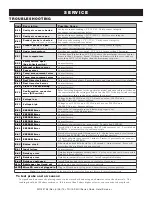
Page 30: ...ge low Voltage below 90 VAC on a 125 VAC unit or below 190 VAC on a 208 240 VAC unit Correct voltage e 79 Voltage high Voltage over 135 VAC on a 125 VAC unit or over 250 VAC on a 208 240 VAC unit Correct voltage e 80 eeproM error Ensure that all temperatures and times are properly set Contact factory if problem persists e 81 eeproM error Contact factory e 82 eeproM error Contact factory e 83 eepro...

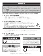
Page 31: ...the hi limit reset button at the rear of the oven After resetting the cause of the high limit trip must be corrected If the high limit switch will not reset the high limit switch is defective and must be replaced This is a safety device and must not be bypassed or removed from the circuit C To test air sensor Test air sensor by placing sensor in ice water bath and using an ohmmeter set on the ohm ...

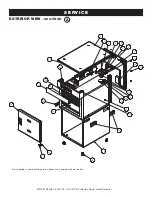
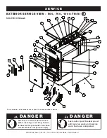
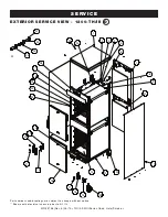
Page 32: ...5 TH III SK III Series Cook Hold Smoke 30 serVIce eXterIor VIew 300 TH III 11 7 10 6 8 1 29 16 25 18 23 21 22 20 19 26 15 9 5 4 3 2 28 13 14 12 17 24 27 18 a Part numbers and drawings are subject to change without notice ...

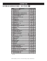
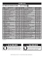
Page 33: ...LAT SC 2254 2 14 BLOCK SENSOR BK 29605 1 15 SENSOR SN 33541 1 16 INSULATION IN 22364 1 17 PRODUCT PROBE 15892R 1 18 HANDLE PULL RECESSED HD 28789 4 19 OUTER CASING SPOT 5014538 1 20 FEET 3 1 2 89mm RIGID FE 29203 4 21 HINGE PLATE BOTTOM RIGHT 1012999 1 LEFT 1014661 1 22 SCREW M6 X 1 0 X 10 PAN SC 27078 2 23 DOOR ASSEMBLY 5014458 1 DOOR GASKET GS 35092 1 24 DRIP PAN PN 2122 1 25 PANEL OVERLAY PE 35...

Page 34: ...20 27 23 25 21 26 24 28 29 31 30 32 33 16 8 21 500 TH III Shown Part numbers and drawings are subject to change without notice danger Disconnect unit from power source before cleaning or servicing Failure to observe this precaution can cause electrical shock and personal injury danger Lock out or post breaker panel until service work until service work has been completed B ...

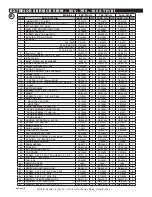
Page 35: ... NF PHIL SC 2073 10 SC 2073 10 SC 2073 10 22 DRIP TRAY KIT 5010736 1 5010391 1 5009716 1 DRIP TRAY HOLDER 1010782 1 1010584 1 1010188 1 DRIP TRAY 1010783 1 1010585 1 1010189 1 23 DOOR ASSEMBLY SLAB RH 5010828 1 5010946 1 5010081 1 DOOR ASSEMBLY WINDOW RH 5010830 1 5010948 1 5010082 1 DOOR ASSEMBLY SLAB LH 5010824 1 5010947 1 5010071 1 DOOR ASSEMBLY WINDOW LH 5010829 1 5010949 1 5010076 1 DOOR GASK...

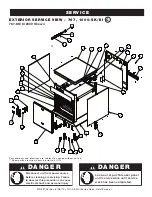
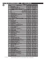
Page 36: ...e before cleaning or servicing Failure to observe this precaution can cause electrical shock and personal injury A 8 7 9 1 4 12 11 30 29 28 27 24 15 14 13A 13B 18 17 19 20 23 22 21 19 5 6 2 3 26 25 10 A 32 33 34 35 16 eXterIor serVIce VIew 767 1000 sK III serVIce 767 SK III 230V Shown Part numbers and drawings are subject to change without notice Shown with electrical chassis prior to 5 1 13 C ...

Page 37: ...PAN SC 22779 2 SC 22779 2 22 HANDLE OFFSET MAGNETIC LATCH HD 27080 1 HD 27080 1 23 SHIM HANDLE 13947 1 13947 1 24 DRIP PAN WELD 14831 1 5005616 1 25 REED SWITCH DOOR SW 33559 1 SW 33559 1 26 BUSHING 3 8 BLACK HOLE BU 3419 1 BU 3419 1 27 SHELF WIRE S S SH 2324 2 SH 2325 2 SHELF RIB RACK SH 2743 2 SH 29474 1 28 SIDE RACKS SR 28405 2 SR 2266 2 PAN SLIDES 230V ONLY 1010813 2 29 PANEL OVERLAY PE 27178 ...

Page 38: ...36 eXterIor serVIce VIew 1200 TH III serVIce A 7 10 1 5 11 8 28 27 24 26 25 22 12B 12A 16 15 17 18 21 20 19 17 9 13 4 3 2 23 30 29 6 A 31 32 33 34 14 Part numbers and drawings are subject to change without notice Shown with electrical chassis prior to 5 1 13 D ...

Page 39: ...N 125 WS 22297 2 12 CASTER PACKAGE 5014421 1 33 WASHER M6 SPLIT LOCK S S 18 8 WS 22302 2 12A CASTER 3 1 2 89mm RIGID CS 24874 2 34 NUT THREADED INSERT NU 22770 1 12B CASTER 3 1 2 89mm SWIVEL W BRAKE CS 24875 2 35 SENSOR GUARD 1493 1 12C SHIM 1012735 4 36 PROBE WIRE HOLDER 13239 1 13 BOTTOM PANEL 1009941 1 37 HIGH LIMIT PROTECTION COVER 1003936 1 14 DRIP PAN WELD 5005616 2 38 PROBE COVER 5009712 1 ...

Page 40: ... 9 31 30 28 29 25 23 14 13A 17 16 18 19 22 21 20 18 10 13B 5 4 3 27 33 32 7 A 34 35 36 37 2 15 24 26 eXterIor serVIce VIew 1200 1767 sK III serVIce 1200 SK III Shown Part numbers and drawings are subject to change without notice Shown with electrical chassis prior to 5 1 13 e ...

Page 41: ...KIT 5010391 1 5009716 1 DRIP TRAY 1010584 1 1010188 1 DRIP TRAY HOLDER 1010585 1 1010189 1 24 DRIP PAN WELD 14831 2 5005616 2 25 SHELF WIRE S S SH 2324 4 SH 2325 4 26 SHELF RIB RACK SH 2743 2 SH 29474 2 27 REED SWITCH DOOR SW 33559 2 SW 33559 2 28 BUSHING 3 8 BLACK HOLE BU 3419 2 BU 3419 2 29 SIDE RACKS SR 28405 4 SR 2266 4 PAN SLIDES 230V ONLY 1010813 4 30 PANEL OVERLAY PE 27181 1 PE 29386 1 31 C...

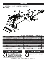
Page 42: ...717 1 4 CORDSET 120V CD 3397 1 12 CONNECTOR 7 PIN CR 33762 1 230V CEE 7 7 CD 3922 1 13 CONNECTOR 8 PIN CR 33761 1 230V CH2 16P CD 36231 1 14 BEEPER BP 3567 1 230V BS1363 CD 33925 1 15 HEATSINK HE 33926 1 5 T BLOCK BK 3019 1 16 RELAY RL 33829 1 6 SCREW 6 32 X 1 1 4 ROUND HD SC 2365 2 17 BOARD POWER SUPPLY BA 36144 1 7 BUSHING HOLE 3 4 BU 3008 1 18 BOARD VOLTAGE MONITOR BA 33764 1 8 BUSHING HOLE 1 2...

Page 43: ... VOLTAGE MONITOR BA 33764 1 230V BS1363 CD 33925 1 15 SPACER LOCK MOUNT SP 33832 4 4 T BLOCSSK BK 3019 1 16 BOARD POWER SUPPLY BA 36144 1 5 SCREW 6 32 X 1 1 4 ROUND HD SC 2365 2 17 HEATSINK HE 33926 1 6 BUSHING 3 4 HOLE BU 3008 1 18 RELAY RL 33829 1 7 BUSHING 1 2 HOLE BU 3006 1 19 HEATSINK BASE 1014450 1 8 CONNECTOR 6 PIN CR 33719 1 20 STAR LOCK WASHER WS 2467 1 9 CONNECTOR 10 PIN CR 33717 1 d an ...

Page 44: ...6 SCREW M4 X 0 7 X 10mm PAN SC 22273 8 19 STAR LOCK WASHER WS 2467 1 7 CONNECTOR 6 PIN CR 33719 1 21 CORDSET 120V NEMA 5 20 CD 3397 1 8 CONNECTOR 10 PIN CR 33717 1 230V CEE 7 7 CD 3922 1 9 CONNECTOR 7 PIN CR 33762 1 230V CH2 16P CD 36231 1 10 CONNECTOR 8 PIN CR 33761 1 230V BS1363 CD 33925 1 11 CONNECTOR 9 PIN 1200 TH III ONLY CR 33718 1 22 CONNECTOR 12 FERRULE CR 34830 3 12 BOARD VOLTAGE MONITOR ...

Page 45: ... 35022 1 21 HEATSINK PAD RELAY HE 33926 1 SMOKER ELEMENT 120V EL 25023 1 22 HEAT SINK SSR BASE 1014450 1 8 SCREW 6 32 X 1 2 PHIL TRUSS SC 2472 12 23 CORDSET 120V NEMA 5 20 CD 3397 1 9 RELAY 230V 25A RL 33829 1 230V CEE 7 7 CD 3922 1 10 BEEPER BP 3567 1 230V CH2 16P CD 36231 1 11 CONNECTOR 6 PIN CR 33719 1 230V BS1363 CD 33925 1 12 CONNECTOR 10 PIN CR 33717 1 24 CONNECTOR 12 FERRULE CD 34830 3 13 C...

Page 46: ...NSULATING SLEEVE 4 12 4 TA 3540 ELECTRICAL TAPE 1 ROLL 1 ROLL 1 ROLL d an g er Disconnect unit from power source before cleaning or servicing Failure to observe this precaution can cause electrical shock and personal injury danger Lock out or post breaker panel until service work until service work has been completed IteM descrIptIon Qty 5015562 HACCP DATA LOGGER RETRO FIT KIT 1 CC 37264 HACCP DAT...

Page 47: ...MN 29758 Rev 6 05 15 TH III SK III Series Cook Hold Smoke 45 ...

Page 48: ...MN 29758 Rev 6 05 15 TH III SK III Series Cook Hold Smoke 46 ...

Page 49: ...MN 29758 Rev 6 05 15 TH III SK III Series Cook Hold Smoke 47 ...

Page 50: ...MN 29758 Rev 6 05 15 TH III SK III Series Cook Hold Smoke 48 ...

Page 51: ...MN 29758 Rev 6 05 15 TH III SK III Series Cook Hold Smoke 49 ...

Page 52: ...MN 29758 Rev 6 05 15 TH III SK III Series Cook Hold Smoke 50 ...

Page 53: ...MN 29758 Rev 6 05 15 TH III SK III Series Cook Hold Smoke 51 ...

Page 54: ...MN 29758 Rev 6 05 15 TH III SK III Series Cook Hold Smoke 52 ...

Page 55: ...MN 29758 Rev 6 05 15 TH III SK III Series Cook Hold Smoke 53 ...

Page 56: ...MN 29758 Rev 6 05 15 TH III SK III Series Cook Hold Smoke 54 ...

Page 57: ...MN 29758 Rev 6 05 15 TH III SK III Series Cook Hold Smoke 55 ...

Page 58: ...MN 29758 Rev 6 05 15 TH III SK III Series Cook Hold Smoke 56 ...

Page 59: ...iday rates or any additional fees To be valid a warranty claim must be asserted during the applicable warranty period This warranty is not transferable THIS WARRANTY DOES NOT APPLY TO 1 Calibration 2 Replacement of light bulbs door gaskets and or the replacement of glass due to damage of any kind 3 Equipment damage caused by accident shipping improper installation or alteration 4 Equipment used un...

Reviews: