- 59 -
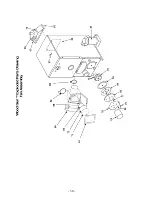
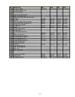
KEY DESCRIPTION
E100
E140
E180
E250
61
Draft Box Lid Gasket
200-052-32
200-052-32 200-052-32 200-052-32
62
Right Side Insulation Jacket
63
Fiberglass Insulation
64
65
Exhaust Hood Attachment Bolts
66
Exhaust Hood Blower (wired)
67
Exhaust Hood Connecting Flange Assembly
68
Draft Motor
200-422B
200-422B
200-422B
200-422B
69
Inner Disc
412-132
412-132
412-132
412-132
70
Gasket Disk, Silicone Disc for Air Valve)
412-145
412-145
412-145
412-145
71
Air Valve Gasket Disc (Includes 70, 69)
413-040
413-040
413-040
413-040
72
Draft Motor Arm Assembly
73
Fan Set Screw
200-499
200-499
200-499
200-499
74
Fan Motor
200-482
200-482
200-482
200-483A
75
Fan Cover Retaining Nuts
76
Fan Cover Plate
77
Motor Mounting Bolts/Screws
78
Fan
A443-006
423-009
423-009
433-005
79
Exhaust Hood, complete
453-019
453-019
453-019
453-019
80
Draft Valve Assembly, complete
81
Cyclone Assembly Complete
423-024
423-024
423-024
453-001
82
Cast Iron Damper 5 Inch
83
Air Valve Box Mounting Gasket
200-052-21
200-052-21 200-052-21 200-052-21
84
Draft Box Mounting Bolts
85
Air Valve Box Complete
86
Smoke Flap
422-053
422-053
422-053
422-053
87
Smoke Flap Retaining Pin
88
Gasket Disk Mounting bolt
89
Gasket Disk
90
Gasket Disk Washer
91
92
93
Fan Ceramic heat Shield
422-125
422-125
422-125
432-185
94
Abrasion Shield
423-023
423-023
423-023
313-010
95
Fan Assembly Gasket
273-024-42
273-024-42 273-024-42 273-024-51
Summary of Contents for wood gun E100 SF
Page 2: ......
Page 24: ...Photo Smoke flap installed 19 ...
Page 46: ...Steel Center Brick 8 Inch 41 ...
Page 49: ...Appendix A Boiler Specification Diagram 44 ...
Page 50: ... 45 ...
Page 51: ... 46 ...
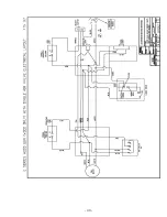
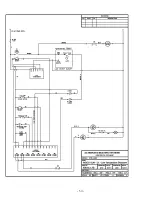
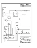
Page 53: ...Appendix B Wiring Diagrams 48 ...
Page 54: ... 49 ...
Page 55: ... 50 ...
Page 56: ... 51 ...
Page 57: ... 52 ...
Page 58: ... 53 ...
Page 59: ... 54 ...
Page 60: ... 55 ...
Page 61: ...Appendix C Exploded Parts Drawings 56 ...
Page 63: ... 58 ...
Page 68: ...Appendix F Boiler Piping and Ducting Examples 63 ...


