background image

- 51 -

Summary of Contents for wood gun E100 SF

Page 1: ...ery hot temperatures Boiler temperatures and flames in the ignition box area are capable of causing ignition or explosion of explosive or flammable products or explosion of the boiler itself if maximum safe water temperature is exceeded Maximum safe water temperature is 200 Fahrenheit Flammable or explosive products must never be stored in the same room or in the vicinity of a boiler and the boile...

Page 2: ......

Page 3: ...Copyright 2000 2015 Alternate Heating Systems No portion of this publication may be reproduced without the express written consent of Alternate Heating Systems Revision 07 31 15 ...

Page 4: ...Expansion Tank Selection 12 Return Water Temperature 12 LOW WATER CUT OFF 12 Recommended Boiler Control Settings in Hydronic Systems 13 Boiler Conditioner Sealant 13 Boiler Piping and Controls for Low Pressure Steam Systems 13 Forced Hot Air Systems Water to air Coil in Duct 14 Domestic Hot Water Coil Piping 14 Oil Burner Assembly 15 General Information 15 Models E180 and E250 15 Oil Gas Burner Co...

Page 5: ...ning and Maintenance 33 Yearly Cleaning 34 Air Valve Motor Replacement 34 Removing Old Damper Motor 34 Installing the New Damper Motor 34 Door Adjustment 35 Load Door Seal Replacement 36 Front and Rear Inspection Door High Temperature Rope Installation 38 Fan Assembly 39 Direct Drive Fan bearing replacement procedure 40 Refractory Replacement 43 Center Brick 43 Side brick Refractory Replacement 45...

Page 6: ...stion in burning wood In a conventional wood stove a signi cant portion of the combustible gases released from the wood goes up the chimney unburned to become deposited on the chimney walls as creosote or escape as visible smoke In the Wood Gun a greater percentage of the combustible elements released from the wood are combusted due to the high temperatures a7ained usually within even a few minute...

Page 7: ...ant gases produced are carbon monoxide methane methanol formaldehyde and hydrogen as well as formic and acetic acids water vapor and carbon dioxide All of these elements must pass through the refractory combustion chamber where in the presence of high temperatures and oxygen they are reduced to carbon dioxide and water By the time the temperature of the fuel reaches 900º F 500º C pyrolysis is comp...

Page 8: ...irements are low it may be necessary to add a dra9 cycle timer to the electrical control circuit to make the unit run for 8 to 10 minutes every two to four hours is will prevent the re from going out and more importantly will maintain su cient temperature in the refractory to ensure complete combustion on start up is feature will provide heat until the timer reaches the end of the programmed cycle...

Page 9: ...ing door seals or Air Valve leaks Insulate stove pipe and or chimney to preserve heat Insulate cyclone Increase load Increase run cycle length Use drier fuel Clean boiler or take other measures to improve air Gow If you are observing back pu ng take care of this issue promptly as performance is compromised in a back pu ng boiler possibly contributing to condensation Keep refractory relatively clea...

Page 10: ...ion of any by products of combustion Boiler Room Requirements 1 e room should be well lit and should have a source of emergency light 2 A convenient water supply should be available for boiler Gushing and to clean the boiler room Goor 3 Unobstructed Goor drains 4 A boiler must not be installed where there is the possibility of the accumulation of explosive vapors 1 Must have adequate air supply wh...

Page 11: ...es for all models are Front 48 Inches Rear 36 Inches Left 12 Inches Right 18 Inches Top 24 Inches Most municipalities require a speci ed clearance between the Gue pipe and combustibles normally 18 in e customer installer must follow all local and state building codes for clearances e above dimensions are to be regarded as minimums Extra clearance is recommended to allow for easy movement around th...

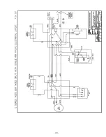
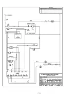
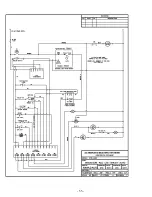
Page 12: ...te between studs and apply equal pressure until the gasket seals rmly against the end of the swirl chamber e wires leading from the fan motor must be inserted into the electrical box on the rear of the unit and connected as according to the wiring diagram for the model being installed see Appendix B Wiring Diagrams INSTALLATION AND MAINTENANCE OF ELECTRICAL CONTROLS AND GAUGES Insert the temperatu...

Page 13: ...masonry chimney that lacks an insulated liner Having such a chimney on the outside of the house compounds this problem as well Because of the high e ciency of the Wood Gun and resultant low stack temperatures it is important to try to preserve exhaust heat Always check with your local building inspector and insurance agent to assure compliance Stovepipe should be sized as follows E100 to E180 not ...

Page 14: ... the vertical section leading from the cyclone Each joint should be secured with three sheet metal screws and sealed with high temperature furnace cement or Troweleze refractory cement or High Temperature Silicone e opening on the T joint should be 7ed with a removable cap to enable cleaning and inspection If the horizontal run to the chimney is inclined it will encourage any Gy ash which drops in...

Page 15: ...mbustion air is ducted from the outside then follow the same procedure as described for passing a smoke pipe through a combustible wall Should the air valve malfunction and not close completely there is a possibility that this conduit could act as an exhaust stack and heat up Consult Appendix F for a picture diagram When the intake air is ducted from the outside inspect the opening regularly to be...

Page 16: ... temperature of the existing boiler at will shut the Wood gun down if it runs out of fuel e aqua stat will need to have a bypass switch that will allow the wood boiler to have power and enable it to be started so that it can be warmed to its operating temperature ere are many possible con gurations that allow for an existing boiler to function as a backup to the Wood Gun For sample illustrations o...

Page 17: ...returning to the boiler should be not more than 20º F less than supply water temperature going to the system A recirculation loop is a requirement to maintain optimum return water temperatures is would optimally include a thermometer on the return line entering the boiler for monitoring purposes and a mixing valve to maintain minimum return water temperatures Return water temperature near or below...

Page 18: ...ackup the control se7ings should be as follows High limit 200 F Operating Limit 180 170 F Burner Control L6006A 150 F In this way the oil burner will function as a backup and only re when the boiler temperature drops below about 150º F e oil burner may be set even lower if desired to prevent it from ring except when the wood re is almost completely out Wood Gun units supplied with automatic switch...

Page 19: ... installing a heat exchange coil in the supply duct e size and type of coil required may be determined a9er several factors are determined ese factors include the heat output required BTUH the capacity of the existing fan blower CFM and the size of the duct or plenum where the coil will be installed e coil creates increased resistance to air Gow so this factor must be considered when determining t...

Page 20: ...d be paid to the Oil Line Connections section of the Riello Installation Manual Ensure that the correct size nozzle is in place on the burner before installing on the boiler Correct nozzle sizes for Riello Oil Burners are E100 0 65 gph 45º semi solid E140 1 00 gph 45º semi solid E180 1 10 gph 45º semi solid E250 1 65 gph 60º semi solid Models E180 and E250 On models E180 and E250 the oil combustio...

Page 21: ...ceramic lined chamber see Figure 10 Oil Burner Electrical Connection Connect the burner in accordance with wiring diagrams found in Appendix B Wiring Diagrams e T terminals on the protector relay of the oil burner may need to be crossed with a jumper wire to activate the burner on certain models e Aux auxiliary wire may not need to be terminated Oil Burner Fuel Line Connection e fuel lines should ...

Page 22: ... the dra9 inducing fan increases the air velocity past the nozzle Because of this increased air velocity the Burner Adjustment Tables in the Riello manual are a good starting point for initial ring of the burner however ne tuning of the burner se7ings is usually needed For proper burner adjustment a combination test kit must be used It is not likely that the CO2 levels suggested in the burner manu...

Page 23: ...scenario causing the switchover to take place is when the boiler has used up the wood fuel e Wood Gun will also switchover to oil if the re goes out as may occur when the boiler has been inactive for hours and the refractory has cooled to below the kindling temperature for wood In this case the boiler must be manually switched back to wood mode and manually relit in order to resume wood burning e ...

Page 24: ...Photo Smoke flap installed 19 ...

Page 25: ...r is not ring If the indicator light does not come on when the purge timer is activated it means the oil gas burner is ring and the door must not be opened e green light at the upper le9 corner of the boiler indicates when the dra9 inducing fan is running e only time the load door can be safely opened is when the indicator light is on If the indicator light is o turn the purge timer clockwise to n...

Page 26: ... on the refractory in a lengthwise orientation Add a layer of crumpled up newspaper followed by another small layer of kindling Light the paper Turn on the boiler switch When the kindling is burning well add more and larger pieces of wood When ring a cold boiler it is important to concentrate heat next to the refractory e Wood GunTM depends on high refractory temperatures for driving the gasi cati...

Page 27: ...d in the fuel chamber during the o cycle Even if the green light is on open the door cautiously since abruptly introducing air over the glowing fuel particles may cause it to temporarily Game up When reloading the Wood Gun it is a good idea to use the ash rake to make sure that all of the center slots are open and free from ash and charcoal before adding more wood Such raking is required more o9en...

Page 28: ... over drying of the fuel charge that occurs with long cycles Use the EPA Side Tunnel Plug described below One way to appraise what is going on inside the boiler is to open the air valve box during an active ring cycle or to look through an optional Air Valve View Port and observe the re If you see Games shooting upward inside the fuel chamber consider the above checklist items as your action list ...

Page 29: ...ller Wood Guns with the belt drive option has one or two variable sheave pulleys which can be adjusted to change the speed of the fan When the unit is assembled and tested at the factory an arbitrary se7ing is made to check for vibration e nal se7ing can only be made once a sample of the fuel to be burned is available In addition to manipulating fan speed by swapping sheaves Alternate Heating Syst...

Page 30: ...ic Feed Systems Abbreviations LR Light Receiver LT Light Transmi7er TDR Time Delay Relay CR Control Relay 1 Photo sensors mounted on the two air valves control the feed system operation 2 With the chamber empty the Light Receiver LR will pick up the signal from the Light Transmi7er LT and begin the feeding cycle 3 Time Delay Relay TDR 2 delays any further action for about 20 seconds to prevent con...

Page 31: ...re box e auger is controlled by a signal produced by the beam contacting the detector module of the photoelectric eye system As the fuel level falls in the fuel chamber the beam is detected and the auger delivers fuel until the pile interrupts the beam e time delay relay prevents rapid cycling of the auger by permi7ing a pre set delay period to elapse before restart e relay is adjustable so that t...

Page 32: ... until all cinders have thoroughly cooled to prevent inadvertently starting a re CONDITIONING OF BOILER WATER Proper treatment of feed water and boiler water is necessary to prevent deposits and corrosion within the boiler e neglect of adequate external and internal treatments can lead to operation faults or total boiler failure Where a choice is available pretreatment external to the boiler is al...

Page 33: ...g carry over or boiler sludge in steam boilers Occasional blow downs of the boiler may remedy these conditions We recommend you utilize the services of a local professional plumbing service for this boiler maintenance task See h7p www p2pays org ref 34 33027 pdf Solids can be categorized as either suspended or dissolved Suspended solids are those that can be removed by ltration while dissolved sol...

Page 34: ...7ing into the boiler water Oil causes foaming or combines with suspended solids to form a sludge which can cause the overheating of boiler plates If oil does get into the boiler the boiler should immediately be taken out of service and thoroughly cleaned 29 ...

Page 35: ...obble so it can move and nd its own seal See Air Valve Cleaning and Maintenance below 9 Inspect the fuel chamber and remove any ash residue Pay special a7ention to corners as ash can easily become trapped here 10 Remove ash pan from the cyclone separator and dispose of its contents 11 Clean excessive ash out of re box Air Valve Cleaning and Maintenance To Operate the Air Valve Manually for Cleanin...

Page 36: ...sket you require To replace the gasket simply remove the center bolt and nut as indicated in the exploded assembly in this manual Do not rmly tighten the nut on re installation as the new gasket needs some slight wobble to seal properly over the air inlet tube YEARLY CLEANING Following is the recommended procedure for yearly cleaning 1 Clean the heat exchanger Remove the dra9 fan assembly Use a wi...

Page 37: ...on the motor e pins must align properly If the pins do not align properly you will experience issues as such Motor may not operate Green Indicator light may not turn on when damper is in the open position Air Valve Motor Clamp Alignment Air Valve Disk in Open Positioning DOOR ADJUSTMENT For proper operation of the Wood Gun it is important to have an e ective seal of the loading door and cleanout d...

Page 38: ...cate the door handle wear pad door hinges and door handle with the grease LOAD DOOR SEAL REPLACEMENT 1 Allow door to completely cool before you touch or start installation remove door 2 Cut Gat berglass tape white tape into 4 equal strips e tape shall stop 1 from each corner 3 Insert silicone tube into a Caulking Gun Load Door with Old Seal Removed and High Temperature Silicone 4 Run a small bead ...

Page 39: ...y raised or uneven areas ese appear as bumps in the contour of the silicone bead Adding Preformed Silicone Bead to Door 7 e gasket should meet evenly if it doesn t you may trim excess Place a small amount of silicone on one of the edges to create a seal Marking to Trim Trimming Preformed Silicone Bead Adding High Temperature Silicone to Butt Joint of Trimmed Bead 8 Once the gasket is in place put ...

Page 40: ...n the hinge side of the door Press the rope in by hand from the center of the door to the rst corner Stretch the rope as much as you can while pushing it in Go from corner to corner until reaching the end When pu7ing the two ends together tuck all loose ends down inside or between the rope ends e rope should protrude about 3 8 above the door frame 5 Gently tap the rope with a mallet to push it in ...

Page 41: ...approximately every two years On belt drive fans the pillow block bearings and belt should be checked every three months A9er the initial burn of two to six hours shut the boiler down and re tighten the pillow block bearing set screws To tighten the fan belt loosen the four bolts that hold the motor to the bracket Slide the motor down and re tighten being careful that the motor is properly aligned...

Page 42: ...n of components for reassembly Mark Assembly Orientation Place the fan assembly on your workbench with the fan facing up Remove the two set screws from the fan hub It might be a good idea to let a good penetrant soak down into the area between the hub and the sha9 Le7ing it soak in for an hour or longer is recommended Fan Hub Set Screws At this point you have a choice of two methods for removing t...

Page 43: ...ou to remove the abrasion shield and the heat shield from the motor plate Be careful when removing the ceramic heat shield It is very fragile It is advisable to use a pu7y knife to separate the heat shield from the motor plate Separate Heat Shield from Motor Mount Plate To remove the motor from the motor mounting plate use an allen wrench to remove the four motor mounting bolts that are counter su...

Page 44: ...i9ed gently out of the motor frame Be sure that the beveled waster remains inside the motor housing Lifting the End Shield with Armature Removing the two screws located beside the sha9 will allow you to separate the sha9 with the still a7ached bearing from the end shield Loosening Screws Securing Bearing to End Shield Use a pulley puller or our custom bearing puller tool 01 100 80101 to remove the...

Page 45: ...ely be the rst refractory components to show signs of deterioration Surface spalling is common under normal conditions and is not reason for concern e Center Brick refractory pieces should be changed every 10 15 cords of wood and must be ordered from Alternate Heating Systems Center Brick are removed by simply li9ing them out ey are likely to have become snug as wood ash will se7le into voids arou...

Page 46: ...Steel Center Brick 8 Inch 41 ...

Page 47: ...the cement to dry for eight hours before ring the unit If the gaps are very large the refractory cement may not appear to dry completely in the eight hours allowed You may go ahead and build a re in the boiler to facilitate curing Please wear the proper safety equipment while performing this task Proper equipment includes work gloves safety glasses and steel toe boots 1 Installing the dry insulati...

Page 48: ... will be able to move the ash rake through them 4 Applying the Troweleze will be your last step e Troweleze will ll in the gap between the brick and the vessel at the front and rear inspection door is is also used to ll in and smooth out any transition from brick to brick If there are areas in the tunnel that catch the ash rake just apply some Troweleze to smooth it out FUEL DIVERTER BLOCKS AUTO F...

Page 49: ...Appendix A Boiler Specification Diagram 44 ...

Page 50: ... 45 ...

Page 51: ... 46 ...

Page 52: ...ns per minute 1M BTU s at 20 degrees temperature di erential requires 100 gallons per minute Wood Gun E Series Specifications E100 E140 E180 E250 BTU Hour Max 150 000 200 000 230 000 350 000 BTU 8 Hour Avg Output 100 000 140 000 180 000 250 000 Water Capacity 60 gallons 80 gallons 90 gallons 140 gallons Fire Box Capacity 6 5 ft3 10 ft3 14 ft3 22 ft3 Fire Box Length 28 32 32 48 Standard Door Openin...

Page 53: ...Appendix B Wiring Diagrams 48 ...

Page 54: ... 49 ...

Page 55: ... 50 ...

Page 56: ... 51 ...

Page 57: ... 52 ...

Page 58: ... 53 ...

Page 59: ... 54 ...

Page 60: ... 55 ...

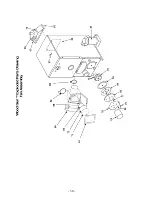
Page 61: ...Appendix C Exploded Parts Drawings 56 ...

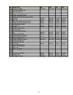
Page 62: ...ent Ceramic Board 422 119 422 119 422 119 433 026 26 Ceramic Plug Refractory 423 012 423 012 423 012 433 013 27 Refractory Center Plug Complete 423 025 423 025 423 025 432 144 28 Latch Shim thick 412 090 412 090 412 090 412 090 29 Latch Shim thin 412 093 412 093 412 093 412 093 30 Latch 31 Latch Mounting Bolt 32 Inspection Door Safety Stud 33 Center Plug Handle 422 118 422 118 422 118 422 118 34 L...

Page 63: ... 58 ...

Page 64: ...74 Fan Motor 200 482 200 482 200 482 200 483A 75 Fan Cover Retaining Nuts 76 Fan Cover Plate 77 Motor Mounting Bolts Screws 78 Fan A443 006 423 009 423 009 433 005 79 Exhaust Hood complete 453 019 453 019 453 019 453 019 80 Draft Valve Assembly complete 81 Cyclone Assembly Complete 423 024 423 024 423 024 453 001 82 Cast Iron Damper 5 Inch 83 Air Valve Box Mounting Gasket 200 052 21 200 052 21 200...

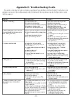
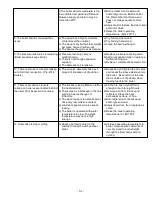
Page 65: ...structions for building a fire b Seal refractory with Trowleze refractory cement c Replace damaged ceramic pad at center cleanout plug d Check doors for airtight seal e Repair replace air valve gasket disc f Clean ash from boiler See weekly maintenance routine 4 Fire goes out a Boiler not cycling frequently enough refractory cools to below kindling temperature b Wood bridging in fuel chamber a Inc...

Page 66: ...e air valve assembly has been moved of knocked out of position a Reposition and tighten the air valve and reseal the sleeve where enters the boiler Be careful not to knock the air valve out of position when loading fuel into the boiler 11 There is excessive creosote buildup on boiler vessel located behind the lower front inspection door area a The fire box is being filled too full for the heat dem...

Page 67: ... to Door 34 Marking to Trim 34 Trimming Preformed Silicone Bead 34 Adding High Temperature Silicone to Butt Joint of Trimmed Bead 34 Finished Joint 34 Reinforcing Corners with High Temperature Silicone 34 Finishing the Corners 35 Finished Level Bead 35 Rear Inspection Door 35 Front Inspection Door 36 Direct drive fan attached to boiler 36 36 Belt drive fan assembly removed from boiler and showing ...

Page 68: ...Appendix F Boiler Piping and Ducting Examples 63 ...

Page 69: ...Wood Gun Air Inlet Ducting Installations 64 ...

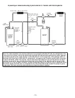
Page 70: ...ivate one or more zones System Circulator and Boiler Circulator 4 Do not bypass temperature supply control system on radiant heat system In radiant heat applications permit activation of a call for heat but allow system controls to regulate water temperature Not all system components valves and devices are shown in this drawing Actual conditions and application requirements will vary Please consul...

Page 71: ...the lower side of the flow control valve A minimum of 1 in diameter pipe should be used for this connection on the model E100 E140 The pipe size must be determined by taking into account the distance involved and flow required The new circulator should be wired to the power for the Wood Gun When power to the Wood Gun is on the circulator should be running An alternate option is to attach a strap o...

Page 72: ... listed in Alternate Heating System s printed literature d the unit is fired with fuels other than those recommended by Alternate Heating Systems This includes fuels recommended by dealers and distributors selling Alternate Heating Systems products if these are not fuels recommended by Alternate Heating Systems C WHAT THE CUSTOMER MUST DO 1 Contact the dealer who sold you the unit 2 If said dealer...

Reviews: