43
Altai Technologies Ltd. All rights reserved
AX500 Series Installation Manual
To enhance the protection, make sure the surge protector is installed as close to the AP as possible. The
Ethernet cable between the surge protector and the AP unit should be of shield type and the length of the
cable run should be made as short as possible. At last, don’t forget to ground the surge protector to a
reliable earth ground point at site with a ground wire. For proper installation and grounding, please follow
the installation guide provided by your surge protector supplier. If necessary, you may also consult premises’
electrical engineers and follow local electrical codes and standards for proper grounding on site.
The table below lists the minimum requirement of Ethernet surge protector to use with AX500 product series
without incompatibility issue. You can also contact us for the suitable models on offer if necessary.
Min Specifications of Surge Protector
2 x RJ45 Jacks for Interface Connection; one to the AP device and
another one to the PoE switch/Injector
CAT6 and CAT5e compatibility
IEEE 802.11af/at PoE compliant
PoE Mode A and B support for power
Outdoor-rated and weatherproof if outdoor deployment needed
Standard GR-1089 compliant or equivalent
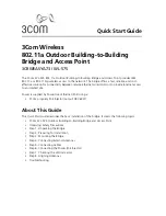
Figure 12-2 Lightning and Surge Protection for AX500 Outdoor Installation
Equipment Room
Ground
AP Unit
Surge Protector
Shielded Ethernet Cable
Conventional
Lightning Spike
Lightning
Protection Zone
Grounding Wire
To Network
Grounding Rod
Lightning Earthing
System
At least 2m
away from pole
Separated Earthing System
for Telecoms Equipment
Surge Protector at
Building Entry Point
(Optional)
Shielded Ethernet Cable to be
as short as possible
Unshieded
Ethernet Cable
Note
: Ethernet Cable and AP
Earth Lead to be on opposite
side to Lightning Spike Earth Lead