background image


36 


Altai Technologies Ltd. All rights reserved 

AX500 Series Installation Manual 


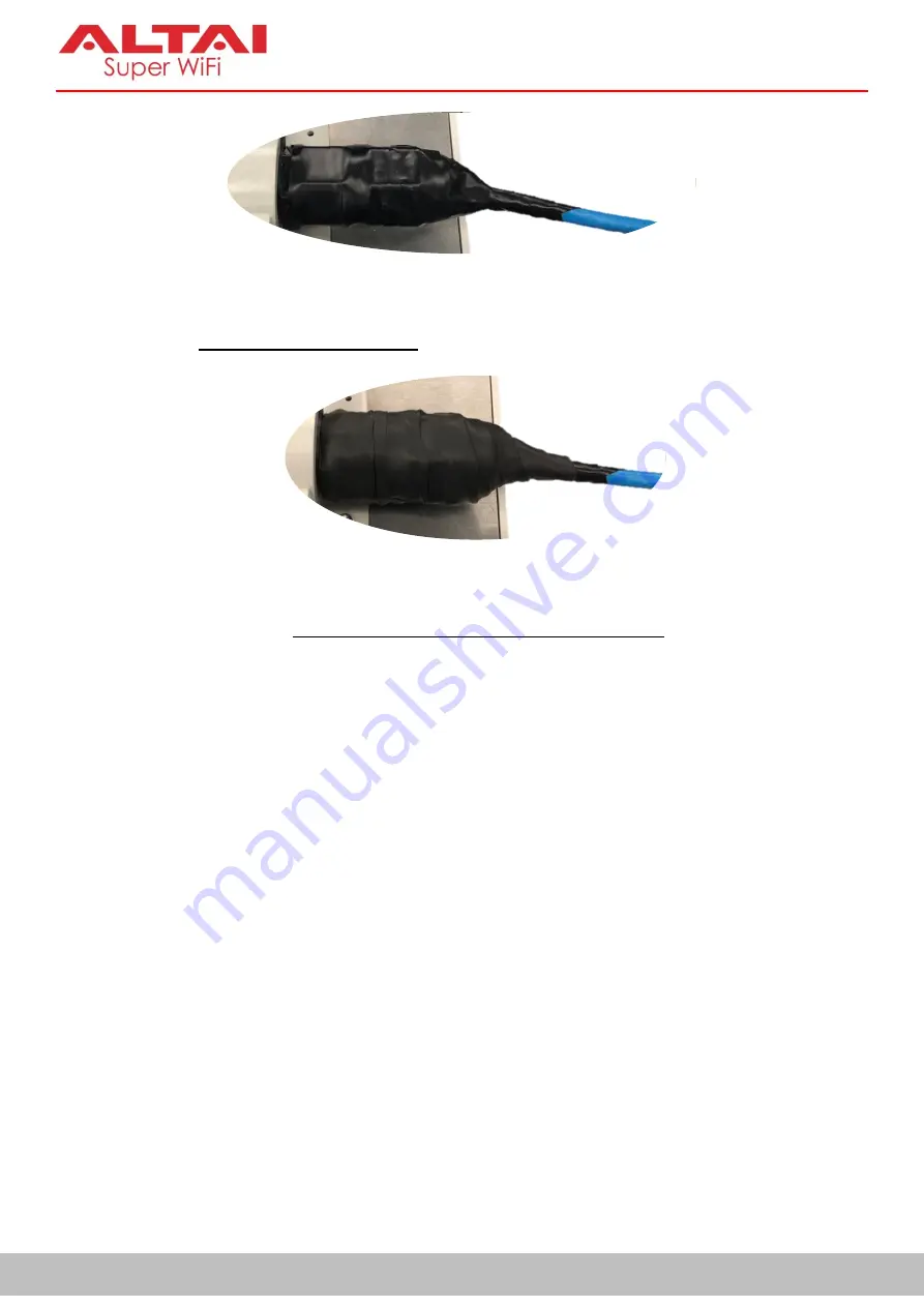
Figure 10-8  Electrical Tape Wrap around Ethernet Port and Cable 


5.


Start wrapping 

a layer of rubber mastic tape

 from the Ethernet cable, 1” (25mm) below the cable gland, 

up to the cable connector. Overlap the tape to half-width. 


Figure 10-9  Rubber Mastic Tape Wrap around Ethernet Port and Cable 


6.


Finish  the  wrap  by  adding 

one  more  layer  (the  3

rd

  layer)  of  electrical  tape

  to  provide  UV  protection. 

Take extra care to make sure that the  Ethernet connector is tightly sealed by pressing the tape edges 
together so that there are no gaps. 


Summary of Contents for AX500 Series

Page 1: ...chnologies Ltd All rights reserved Altai AX500 Outdoor 2x2 802 11ac Wave 2 Access Point ____________________________________________________________________________________ Installation Manual Version...

Page 2: ...connected Consult the dealer or an experienced radio TV technician for help FCC Caution Any changes or modifications not expressly approved by the party responsible for compliance could void the user...

Page 3: ...X Using a different power adaptor might damage the device Disclaimer All specifications are subject to change without prior notice Altai Technologies assumes no responsibilities for any inaccuracies i...

Page 4: ...ON OF AX500 INSTALLATION 10 5 AX500 S INSTALLATION OPTIONS 11 5 1 Antenna Beamwidth and Orientation 11 5 2 Wall Mount Installation 11 5 3 Pole Mount Installation 13 5 4 Installation Scenarios 15 Wall...

Page 5: ...3 Ethernet Cable Feed Through 33 Before Tape Wrapping 34 Tape Wrapping around Ethernet Ports 35 Tape Wrapping around Unused Ethernet Console Ports 37 10 4 Waterproofing RF Ports 38 Before Tape Wrappin...

Page 6: ...v Altai Technologies Ltd All rights reserved AX500 Series Installation Manual THIS PAGE INTENTIONALLY LEFT BLANK...

Page 7: ...0 degree of sector coverage 2 AX500 T Integrated antenna AP model designed to provide 360 degree coverage 3 AX500 X External antenna AP model which is designed to provide more flexibility for deployme...

Page 8: ...the package that you purchased against the corresponding list to ensure the equipment and all its accessories are included Please contact our sales representatives if there is any discrepancy Moreove...

Page 9: ...0 Screw with Washers Shared with Wall Mounting Kit x 4 pcs d Mounting Back Plate x 1 pcs M8 x 110 Mounting Screw x 4 pcs Flat Washer and Spring Washer x 4 pcs Wall Mounting Kit e Mounting Bracket x 1...

Page 10: ...Mounting Kit c Back Mounting Plate x 1 pcs d Pole Mount Bracket x 1 pcs e Hose Clamp x 2 pcs f M4 8 Round Head Screw with Flat and Spring Washers x 8 pcs g Mounting Screw x 4 pcs h P3 5 32 Screw x 4...

Page 11: ...Mounting Kit c Back Mounting Plate x 1 pcs d M4 8 Round Head Screw with Flat and Spring Washers x 8 pcs e Anchor with Flat Washer and Nut x 4 pcs f Pole Mount Bracket x 1 pcs g Hose Clamp x 1 pcs h M...

Page 12: ...Flashing Green Data Transmitting Receiving Off Radio Disabled LAN Ethernet 0 1 Solid Blue Green LAN Connected with 1Gbps 100Mbps of Ethernet Speed Flashing Blue Green Data Transmitting Receiving Off...

Page 13: ...oE It is used to connect to power source see Section 9 for the power options and provides 10 100 1000 Mbps network interface for LAN connection ETH1 It provides 10 100 1000 Mbps network interface for...

Page 14: ...ng For details refer to Section 11 AX500 X Model Bottom View RF Port 4 2 4GHz Antenna Ethernet Port 0 PoE Data In RF Port 6 2 4GHz Antenna Ethernet Port 1 Data In Top Bottom Ground Point RF Port 3 5GH...

Page 15: ...console cable For details refer to Section 14 Port 1 and Port 3 It is used to attach 5G antennae purchased separately for 2x2 MIMO WiFi access coverage or bridge connection For details refer to Sectio...

Page 16: ...concrete wall mount installation Screwdriver Slot type and Phillips type Adjustable wrench Scissors and blade cutter Wire stripping tool and crimping tool Waterproof rubber mastic tape and electrical...

Page 17: ...et coverage area by antenna panning and tilting 2 4GHz 5GHz Horizontal Beamwidth 120 3 dB 120 3 dB Vertical Beamwidth 40 3 dB 20 3 dB 5 2 Wall Mount Installation In this section we will walk you throu...

Page 18: ...bit to drill four holes of 8mm diameter and 37mm depth on the markings and hammer the bolts into the openings Drywall Mount Drive the mounting screws into the wall on the markings 3 Place the spring...

Page 19: ...crete Wall Mount Attach the device onto the wall by tightening the bolt s nuts with flat and spring washers to secure the mounting plate to the mounting surface Drywall Mount Insert the screws through...

Page 20: ...rs on the M4 round head screws and drive the screws to attach the downtilt bracket to the back of the Access Point 3 Align the mounting back plate and the Access Point on the pole Insert the long scre...

Page 21: ...should need so that the front antenna radome is pointed at the target coverage area You can simply determine the downtilt angle by trigonometry formula tan 1 Building Height Target Range The max downt...

Page 22: ...0 S Installation at Building Rooftop Wall Parapet Rooftop AX500 S Surge Protector Ethernet Cable to PoE Switch Injector Clearance of 1m at least depending on AX500 S downtilt angle and building struct...

Page 23: ...tenna radome faces downwards to the target area 6 2 Pole Mount Installation In this section we will walk you through how to assemble the mounting accessories and mount the AP on a pole The pole size s...

Page 24: ...le mount bracket to the mounting plate 3 Thread the open end of the hose clamp through the two slots on the pole mount bracket For the Pole of Vertical Alignment For the Pole of Horizontal Alignment F...

Page 25: ...n two types of ceilings i concrete wall or ii drywall 1 Determine where the AP is to be placed and mark location on the ceiling surface for the four mounting holes 2 Concrete Wall Ceiling Mount Use th...

Page 26: ...e back of the Access Point 4 Concrete Wall Ceiling Mount Attach the device onto the ceiling by tightening the bolt s nuts with flat and spring washers to secure the mounting plate to the mounting surf...

Page 27: ...t more than 10 meters above the target coverage area The AX500 T unit should be mounted on ceilings or installed on horizontal poles instead of vertical ones In addition the size should be 3 4 inches...

Page 28: ...ntenna NS AN 2M08 00 For 2 4G omni access coverage 3 2 4GHz 15dBi Sector Antenna SD AN 2S15 00 For 2 4G sector access coverage 5G Antennae Description Part No Purpose 1 5GHz 9dBi Omni Antenna NS AN 5M...

Page 29: ...er Place the spring and flat washer on the M4 round head screws and drive the screws to attach the mounting plate to the back of the Access Point 1 2 Align the pole mount bracket with the mounting pla...

Page 30: ...le the mounting accessories and mount the AP main unit on two types of wall i concrete wall or ii drywall 4 For Vertical Pole For Horizontal Pole Determine where the AP is to be placed Lock and tighte...

Page 31: ...e wall on the markings 2 Concrete Wall Mount Use the appropriate drill bit to drill four holes of 8mm diameter and 37mm depth on the markings and hammer the bolts into the openings 3 Place the spring...

Page 32: ...ough the flat and spring washers Then attach the device onto the wall by tightening the screws to secure the mounting plate to the mounting surface 4 Concrete Wall Mount Attach the device onto the wal...

Page 33: ...downtilt angle you should need for the sector antenna so that the front radome is pointed at the target coverage area You can simply determine the downtilt angle by trigonometry formula tan 1 Buildin...

Page 34: ...allation Manual Figure 7 2 AX500 X Installation Scenario Building Rooftop for Bridge Link Setup and Sector Coverage Target Coverage Area Local Site with Ethernet Fiber Connectivity Remote Site without...

Page 35: ...protection if the AX500 unit is installed in an outdoor environment For details refer to Section 10 3 3 T568B standard is recommended for RJ45 connector pin assignment See Figure 8 1 for the color co...

Page 36: ...arately 1 Connect the PoE injector ports as described below via Ethernet Cables PoE Injector Ports PoE Go to AX500 Eth0 PoE port LAN Go to backend device such as switch or router or computer or periph...

Page 37: ...is connection option applies to ALL AX500 Series AP Models including AX500 S AX500 T and AX500 X Blue 1000M Green 100M Yellow Standalone AP Green Thin AP AX500 Series AP Ethernet Cable PoE Data Ethern...

Page 38: ...nd the Ethernet and RF ports The port is often first wrapped with a layer of electrical tape to make it easier to remove the second layer which is a butyl rubber layer In addition one or more layers o...

Page 39: ...rtical runs of cable the final layer of electrical tape should be wrapped from the bottom to the top and overlap about 50 of the width of the tape This will provide the same effect as shingles on a ho...

Page 40: ...e clockwise direction as shown in 4 Figure 10 4 Take extra care to make sure that the rubber ring would not hinder the subsequent tightening of the cable gland or cap nut This is to fill out the space...

Page 41: ...Cable Feed through Cable Gland with Rubber Mastic Ring around 3 Plug the RJ45 jack into the Ethernet port Figure 10 7 RJ45 Connector Plugged into Ethernet Port 4 Wrap a layer of electrical tape starti...

Page 42: ...ernet cable 1 25mm below the cable gland up to the cable connector Overlap the tape to half width Figure 10 9 Rubber Mastic Tape Wrap around Ethernet Port and Cable 6 Finish the wrap by adding one mor...

Page 43: ...pe to half width The tape should cover the entire port See Figure 10 10 The tape can be applied in one or more strips if necessary 4 Start wrapping a layer of rubber mastic tape in the same direction...

Page 44: ...equent tightening of the RF connector around the antenna port Figure 10 11 Rubber Mastic Ring around the Base of RF Port Tape Wrapping around RF Ports 1 Make sure each RF cable omni antenna and its co...

Page 45: ...body and part of the RF cable antenna body i e 1 25mm of body length The tape can be applied in one or more strips if necessary A strip can be coiled onto an applicator such as a pencil Apply only en...

Page 46: ...port See Figure 10 15 The tape can be applied in one or more strips Apply only enough tension to get good adhesion and keep the tape smooth 3 Wrap a layer of rubber mast tape from the port base Overl...

Page 47: ...must be installed Use size 10 AWG ground wire not included and attach it to the chassis using the provided ground screw Connect the other end of ground wire to a reliable earth ground point at site P...

Page 48: ...the AP Therefore it is very important that using shielded outdoor rated Ethernet cable together with shielded RJ45 jack for outdoor deployment The differentiation between unshielded twisted pair UTP E...

Page 49: ...series without incompatibility issue You can also contact us for the suitable models on offer if necessary Min Specifications of Surge Protector 2 x RJ45 Jacks for Interface Connection one to the AP...

Page 50: ...allel along the pole Or even better run the Ethernet cable inside of the mounting pole if possible The mounting pole will act as insulation and help passing surges to ground 3 Increased separation of...

Page 51: ...devices are protected under the zone If the installation location is not covered by the lightning rod you should install a standalone lightning protection system for the antenna system See Figure 12 2...

Page 52: ...console cable The RJ45 connector goes to the console port and the RS232 DB9 serial connector goes to the laptop An extra adapter of USB to RS232 DB9 may be required for laptop connection Figure 14 1 C...

Page 53: ...n Password BusyBox v1 25 1 2018 04 23 12 01 11 CST built in shell ash ___ _ _ _ _ ___ _ __ _ _ ___ ___ _ _ _ _ __ _ _ ___ ___ _ ___ _ __ _ _ _ _ _ Mobile Internet for Everyone SuperWifi Base Station V...

Page 54: ...after reset Full Factory Reset Command Description admin SUPERWIFI full_factory _reeset To reset the AX500 unit completely All settings should be removed and returned to the factory default state Fact...

Page 55: ...prung back to its original position when unplugging the Ethernet cables Poor pin contact may cause fallback in Ethernet speed Therefore please have a careful check on the Ethernet pin contact 5 Check...

Page 56: ...nologies Limited ALL RIGHTS RESERVED Altai Technologies Limited Unit 209 2 F Lakeside 2 10 Science Park West Avenue Hong Kong Science Park Shatin New Territories Hong Kong Telephone 852 3758 6000 Fax...

Reviews: