


ALPINE HCE-C500 EN 68-18693Z84-A (A5)
9
-EN
ach
en
A
View
cle.
view
hen
Indication mark meaning
C
Guidelines representing a distance of
approx. 0.5 m all round the vehicle.
Rear View:
Refer to “Rear View” (page 9).
Top View synthesises images from four cameras
and displays the combined view on the monitor.
As the sensitivity of each camera is individually
adjusted to the optimal degree, the image on
the monitor may appear rather unnatural
(brightness, tint, etc.).
With Top View, the camera image around the joins
or borders may not be displayed. For details, refer to
“About Top View Blind Spots” (page 13).
Do not use Top View while retracting the door
mirrors or when the vehicle doors are not completely
closed, as the image will not be displayed properly.
For details of how to switch image patterns, refer to
“Camera Operation” (page 14).
The rear camera image is a mirror image. The image
in the display is reversed, as you would see through
the rearview mirror. As the camera uses a wide-angle
lens, there is a difference between the actual distance
and what appears on the screen.
Images may not be clearly displayed in the following
conditions. This is normal.
In the dark (nighttime, etc.)
The temperature near the lens is high or low.
The camera has water droplets on it or the
humidity is high (rainy day, etc.).
Foreign substances (dirt, etc.) are on or around the
camera.
Sun light or the light of a headlamp directly enters
the camera lens.
The image range will be affected by the height or
inclination of the vehicle. The position indicated
by the distance guidelines, actual distance from
the road surface and distances from objects will
vary, depending on factors such as number of
passengers, load weight and suspension adjustments.
In addition, joins in Top View images may not be
properly aligned. Always visually check the actual
conditions around the vehicle to ensure safety.
p
•
•
•
•
•
•
•
–
–
–
–
–
•
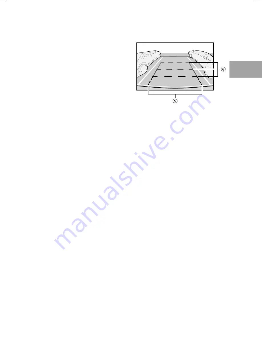
Rear View
Displays the area behind the vehicle.
Use this when reversing into a garage or when
checking for objects behind the vehicle.
Indication mark meaning
E
Car width extension marks (orange,
yellow and green in order of distance)
If properly calibrated, the marks indicate the
car’s width. This helps guide the car’s path
when backing up in a straight line.
F
Distance guidelines
The horizontal lines represent the distance
from the rear of the car (from the rear end of
the bumper).
The lines do not move in synchronisation
with the steering wheel.
Each line represents a distance of 0.5 m
(orange), 1 m (yellow) and 2 m (green)
behind the vehicle.
Depending on the condition of the car or road
surface, the range of vision may vary.
The camera has a limited range of vision. Objects at
extreme angles to the camera (e.g. under the bumper
or at opposite ends of the bumper) may not be in the
its field-of-vision.
The rear camera image may have a tint which is
different from the actual surroundings.
Depending on the car, the guidance may deviate to
the right or left. This is not a malfunction.
e
p
•
•
•
•
•
•


