background image

11

Mobile  Phone  App  

There are 10 input EQ values. Move the slider up 

and down or click a gain value to display the gain 

adjustment box and then move the slider left and 

right or press “+”/“-” to set the gain; click a Q value 

to display the Q value adjustment box and then 

move the slider left and right or press “+”/“-” to set 

the Q value; click a frequency value to display the 

frequency adjustment box and then move the slider 

left and right or press “+”/“-” to set the frequency.

Frequency range: 20 Hz-20 kHz;

Q value range: 0.404-28.852;

Gain range: -12 dB-+12 dB.

Note: In the Graphic EQ interface, the gain 

is adjustable, while the frequency and the Q 

value cannot be adjusted; in the Parameter 

EQ interface, the frequency, Q value and gain 

can be adjusted.

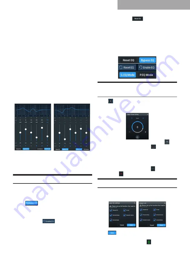
2.  Output EQ edit area 

The output EQ has two interfaces: Graphic 

EQ and Parameter EQ.

P.EQ interface

G.EQ interface

There are 31 output EQ values. The adjustment 

method and range of the frequency, Q value and 

gain are similar to the adjustment of the input EQ.

Setting the Equalizer

1.  When the EQ is being adjusted, the Direct 

EQ button appears.

2.  Direct EQ: When the channel EQ is enabled, 

the 

 button appears. Click “Direct 

EQ” disable all the equalizers of the current 

channel.

3.  Click “Yes”, and the button will then change 

to “Reset EQ” 

. Click “Reset EQ”, 

and all the equalizers of the current channel 

will be reset to the previous state. 

Note: The 

state enabled by clicking “Direct EQ” can 

be reset by clicking “Reset EQ”, while 

the state enabled by clicking the circle 

cannot be reset by clicking “Reset EQ”.

4.  Click “Reset EQ” 

, all the equalizers 

of the current channel are reset to the initial 

state: the input Q value is 2.515, the output 

Q value is 2.201, and the gain is 0.0 dB.

5.  Click P.EQ to shift to G.EQ. In the P.EQ 

mode, the frequency, Q value, and gain can 

be adjusted, while in the G.EQ mode, the 

frequency and Q value are fixed and only the 

gain of the EQ can be adjusted.

Setting the Channel Phase and 

Volume

Click “ ” under the volume to set the channel 

volume or shift the channel phase in the popup 

dialog box.

1.  Phase: Click the positive phase icon “

” or the negative phase icon “ ” to switch 

between the positive and negative phases.

2.  Volume: Move the slider or click “+” / “-” 

to adjust the volume; the volume range: 

-60 dB–6 dB).

3.  Mute: Click the volume icon “ ” to mute the 

channel “ ”.

Setting the Channel Link

Set the input or output functions to be tuned in 

the interface;

Click “

” to select the channel for link setting 

from the popup dialog box. Then the link icon next 

to the channel will be green “

”, indicating the 

link setting is enabled.

Summary of Contents for PXE-X09

Page 1: ...HIGH RESOLUTION WIRELESS DIGITAL SOUND PROCESSOR PXE X09...

Page 2: ...12 Copy and Paste Function 12 Software Instructions Important Instructions for Software Installation 13 Introduction to the Main Interface 13 Connecting to the DSP 14 Setting the Input Mode 15 Setting...

Page 3: ...serious injury In case of swallow please consult a physician immediately This product only applies to 12 V type vehicles Otherwise it may cause fire electric shock or other injury Attention This symb...

Page 4: ...the Equalizer 10 18 Setting the Channel Phase and Volume 10 19 Setting the Channel Link 10 19 Setting the Delay 11 19 Sound Effect Presets 11 20 Note Operations on PC are only available to dealers an...

Page 5: ...3 Introduction to the DSP 1 Connections...

Page 6: ...h level input the LED indicator of the corresponding connection is on when it is set to low level input the LED indicator of the corresponding connection is off 12 13 Optical and Coaxial Connections W...

Page 7: ...the DSP 1 If the Bluetooth icon is red it indicates the Bluetooth is not connected if it is green it indicates that the Bluetooth is connected 2 Click to enter Mixer Signal generator Input link settin...

Page 8: ...N 3 and 4 are set to Full range IN 5 is set to Subwoofer 4 Four CH Left and Right FC 6CH Front Left and Front Right channels of IN 1 and 2 are set to Full range Rear Left and Rear Right channels of IN...

Page 9: ...Front Channels Two Rear Channels Center Channel Left and Right FC 11CH Front Left and Front Right channels of IN 1 and 2 are set to Tweeter Front Left and Front Right channels of IN 3 and 4 are set to...

Page 10: ...el and low level inputs the green triangle symbol indicates the input mode is the main sound source 2 Input mode selection Click and select the input channel type from the popup dialog box by moving t...

Page 11: ...channels of OUT 5 and 6 are set to Full range OUT 7 is the center channel and set to Full range OUT 8 is set to Subwoofer 10 Three Front Channels Two Rear Channels Center Channel FC 12CH Front Left an...

Page 12: ...nnels of OUT 7 and 8 are set to Tweeter Rear Left and Rear Right channels of OUT 9 and 10 are set to Midrange Rear Left and Rear Right channels of OUT 11 and 12 are set to Woofer OUT 13 is the center...

Page 13: ...e equalizers of the current channel 3 Click Yes and the button will then change to Reset EQ Click Reset EQ and all the equalizers of the current channel will be reset to the previous state Note The st...

Page 14: ...ill unmute it automatically 3 Main sound source selection Click the buttons under the main sound source and select the source from the popup window Select the main sound source from the popup window O...

Page 15: ...or higher Memory 1 GB or higher Hard disk 512 MB or more PC resolution 1280 768 or higher Before connecting PXE X09 to PC please install the PXE X09 software correctly Introduction to the Main Interfa...

Page 16: ...ted to the currently connected DSP d Select Save All Presets Save all data files of the connected DSP to your PC all data files of the DSP include all the data including current working scenarios pres...

Page 17: ...lue data The tuning data as delay time channel and phase equalizer settings will also be encrypted The encryption is only effective for the sound effect data currently used instead of all the data of...

Page 18: ...IN 5 and 6 are set to Full range IN 7 is the center channel and set to Full range In 8 is set to Subwoofer 10 Three Front Channels Two Rear Channels Center Channel FC 12CH Front Left and Front Right c...

Page 19: ...level input selection 1 Stereo 2CH Front Left and Front Right channels of IN 1 and 2 are set to Full range 2 Four CH 4CH Front Left and Front Right channels of IN 1 and 2 are set to Full range Rear L...

Page 20: ...t channels of OUT 3 and 4 are set to Mid bass Rear Left and Rear Right channels of OUT 5 and 6 are set to Full range Left and Right channels of OUT 7 and 8 are set to Subwoofer 8 Two Front Channels Re...

Page 21: ...ange OUT 9 is set to Subwoofer 15 Three Front Channels Rear Channels Left and Right FC 10CH Front Left and Front Right channels of OUT 1 and 2 are set to Tweeter Front Left and Front Right channels of...

Page 22: ...e and gains can also be set by directly entering the value scrolling the mouse wheel or pressing Up Down keys on the keyboard Frequency range 20 Hz 20 kHz Q value range 0 404 28 852 Gain range 12 dB 1...

Page 23: ...by directly entering the value scrolling the mouse wheel or pressing the Up Down keys on the keyboard The default volume value is 0dB Adjustment range 60 dB 6 dB 3 Mute Click the volume icon to mute...

Page 24: ...he main sound source the lower the master volume The available values are 30 50 80 100 and Off 2 Click the keys under the auxiliary sound source and select from the popup window Options include Optica...

Page 25: ...nterface as shown in Figure 3 Turn the button to select the main sound source Optical Coaxial BT Bluetooth Hi L High Level and AUX Low Level Note If the wired controller is not operated for about 5 se...

Page 26: ...it from the interface to the main interface Master Volume Interface Figure 5 Sound Effect Presets PRESET After adjusting the subwoofer volume press the button briefly to enter the sound effect presets...

Page 27: ...response 20 Hz 20 kHz System sampling rate 24 bit 96 kHz Optical Coaxial input sampling rate 28 kHz 216 kHz Input impedance High level 240 AUX 47K Output impedance 51 Working voltage 9 16V Quiescent c...

Page 28: ...resolution 1 Hz Q value slope 0 404 28 852 Gain 12 dB to 12 dB resolution 0 1 dB Input output signal crossover Each input output channel has at most 8 independent filters Filter Linkwitz Riley Bessel...

Page 29: ...nts Display components Accessories This table is prepared in accordance with SJ T11364 indicates that the content of the harmful substance contained in all homogeneous materials of the component is be...

Reviews: