Alpha Alpha CombiMax 350 Installation And Servicing Instructions Download Page 6

6

Alpha CombiMax 350 and 600

3.4

UNVENTED HOT WATER STORAGE SYSTEM

The installation is subject to Building Regulations approval and the Local Authority must be notified of the intent to install.

The CombiMax store is supplied with the components required for an unvented hot water system, i.e. temperature/pressure and
expansion relief valves, expansion vessel, check valve and tundish. All these components are factory fitted, except for the expansion
vessel, which is to be connected to the top of the storage cylinder after installation, and the tundish which must be installed as follows:-

Discharge pipe - The discharge pipes from both the temperature/pressure and expansion relief valves have been joined together
within the appliance. The combined discharge pipe from the appliance must be routed to the tundish supplied in 15 mm pipe.

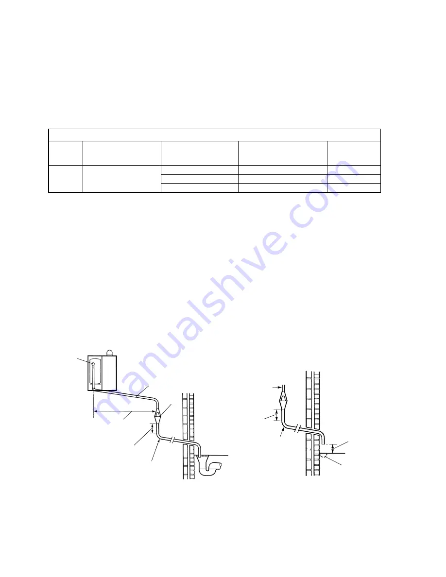
Tundish - The tundish must be positioned within 500 mm of the appliance, so that it is visible to the User and away from electrical
devices. The minimum size of the discharge pipe downstream of the tundish is given in the following table.

Fig. 1a

300 mm

minimum

Tundish

500 mm max.

from appliance

Metal discharge pipe (D2) from

tundish with continuous fall

Metal discharge pipe (D1)

from relief valves to tundish

Temperature/pressure

relief valve

300 mm

minimum

100 mm max.

70 mm min.

Gulley if
available

Pipe close to wall to
allow water to fan out
safely

Ground level

D2

D1

LOW LEVEL TERMINATION

Resistance created

by each elbow

or bend

0.8 m

1.0 m

1.4 m

Maximum resistance allowed,

expressed as a length of straight

pipe (i.e. no elbows or bends)

up to 9 m

up to 18 m

up to 27 m

Minimum size of discharge

pipe 'D2' from tundish

22 mm

28 mm

35 mm

Minimum size of discharge

pipe 'D1' to tundish

15 mm

Valve

outlet size

Sizing of copper discharge pipe 'D2' - refer also to Figs. 1a and 1b

The discharge pipework from the tundish:-

a. Shall fall continuously through its length.
b. Shall be of a heat resistant material, e.g. metal.
c. Shall not be fitted with any valves or taps.
d. Shall discharge to a safe visible position, e.g. onto the surface of an external wall or into a gulley.
e. Shall have a minimum of 300 mm straight pipework directly from the tundish.

Note: Where children may play or otherwise come into contact with discharges, a wire cage or similar guard must be
positioned to prevent contact whilst maintaining visibility.

Refer to Figs. 1a and 1b for suggested methods of terminating the discharge pipe safely.

Where a single pipe serves a number of discharges, such as in blocks of flats, the number served should be limited to not more
than 6 systems so that any installation can be traced reasonably easily. The single common discharge pipe should be at least
one pipe size larger than the largest individual discharge pipe to be connected.

If the system is installed where discharges from safety devices may not be apparent, i.e. in dwellings occupied by blind, infirm or disabled
people, consideration should be given to the installation of an electronically operated device to warn when discharge takes place.

Summary of Contents for Alpha CombiMax 350

Page 1: ...40 280 Range of Gas Fired Combination Boilers Building Regulations Certificate No ETC 03198 These instructions must be used in conjunction with the Installation instructions provided with the selected...

Page 2: ...te the hot water within the loop For full details contact Alpha Therm Ltd The CombiMax storage cylinder has the facility for fitting an electric immersion heater which must be obtained from Alpha Ther...

Page 3: ...r storage 50 C 350 model 600 model Reheat time for 70 of storage 350 model 600 model Min Clearances required for Servicing Top Bottom Sides Front Dimensions CombiMax Height 350 model Width 600 model W...

Page 4: ...r 5 DHW pump 6 Pressure reducing valve with filter and check valve 7 Drain point 8 DHW expansion relief valve 9 Store thermostat 10 DHW expansion vessel 11 Manual air vent 12 DHW temperature pressure...

Page 5: ...approximately 92 kg 350 model or 130 kg 600 model The CombiMax may be installed in any room or internal space although particular attention is drawn to the requirements of the current IEE WiringRegul...

Page 6: ...sistance created by each elbow or bend 0 8 m 1 0 m 1 4 m Maximum resistance allowed expressed as a length of straight pipe i e no elbows or bends up to 9 m up to 18 m up to 27 m Minimum size of discha...

Page 7: ...her with screws wall plugs and washers e Literature pack and DHW control knob label f Boiler conversion kit with restrictor spanner and boiler converted label 2 Unpack the boiler as per the Installati...

Page 8: ...Figs 5 and 6 as follows a Unscrew fitting A and discard the components A B and C as shown in Fig 5 Fig 5 Differential pressure sensor BEFORE modification b Screw fitting D supplied in the conversion...

Page 9: ...left hand side panel removed from the boiler to the CombiMax by hooking the top of the panel over the brown trim of the mounting frame and securing it at the bottom rear of the panel Secure the panel...

Page 10: ...ee Figs 9 and 10 and connect to the boiler terminal block via the grommet as shown in Fig 11 Refer to section 2 4 for connection details The boiler main terminal block can be removed by pulling it off...

Page 11: ...taps and allow water to flow until no air is present Turn off the taps Cover all electrical components beneath the CombiMax pump and then release the pump bleed screw until all the air has been vente...

Page 12: ...minutes and then the burner pressure will decrease slowly to its minimum until the hot water store reaches a temperature of approximately 56 C Check the burner pressure and that the burner goes out wh...

Page 13: ...biMax store Clean the filters within the pressure reducing valve and the mains water inlet valve 5 6 FINAL ASSEMBLY After completing the assembly of the boiler place the CombiMax front casing in posit...

Page 14: ...Refill the store refer to Commissioning section 5 1 8 4 DHW OUTLET THERMOSTAT See CombiMax Schematic illustration 1 Gain access as described in section 8 1 Ensure the electricity supply is isolated 2...

Page 15: ...water circuit by opening the mains water inlet valve 8 11 PRESSURE REDUCING VALVE CHECK VALVE See CombiMax Schematic illustration 1 Drain the CombiMax as described in section 8 2 2 Disconnect the unio...

Page 16: ...16 Alpha CombiMax 350 and 600 9 WIRING DIAGRAMS 9 1 COMBIMAX ILLUSTRATED WIRING DIAGRAM 9 2 COMBIMAX FUNCTIONAL FLOW WIRING DIAGRAM...

Page 17: ...stat TOD DHW expansion vessel 4 litre DHW expansion vessel 5 litre Temperature pressure relief valve 90 C 7 bar DHW outlet thermostat wax element Storage cylinder 35 litre Storage cylinder 60 litre Bo...

Page 18: ...mbiMax produced before February 1999 i e before Serial No A906 must not be fitted remote from the boiler 2 A CombiMax fitted remote has no casing Fig 13 Possible locations for the CombiMax in relation...

Page 19: ...IMUM CLEARANCES REQUIRED 12 5 WALL MOUNTING The wall mounting frame and security strap supplied are to be used to secure the CombiMax storage cylinder to the wall 12 6 CASING The casing components sup...

Page 20: ...er as shown in Fig 16 using 15 mm pipework The pipework supplied with the CombiMax can be utilised to provide the connections at the boiler and CombiMax 12 10 ELECTRICAL SUPPLY Connect the electrical...

Reviews: