Appendix B: S/T Bus
Configuration
Combinations of these settings and the wiring
requirements of the installation determine the
configuration for each line. Each S/T-Interface is
configured separately to provide flexibility.
Default Configuration:
The manufacturer’s default DIP Switch
configuration will work on almost all installations.
No more than four terminals can be attached and
each terminal must be the same distance away
from the NT1, within 10 meters tolerance, to a
maximum of 200 meters divided by the number
of terminals. For example two terminals could
be 85m and 95m from the NT1 respectively.
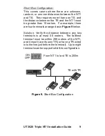
ON
OFF
From
is 200m
N T 1 t o T E
Figure 8.
Default S/T Configuration
Alternative Configurations:
There are three configurations for which the
defaults are not the ideal settings. Each is
detailed with examples and the appropriate
configuration.
8
UT3620
NT1 Installation Guide
Triple
Summary of Contents for UT3620 Triple NT1
Page 1: ...UT3620 Triple NT1 Installation Guide ...
Page 2: ......
Page 23: ...NOTES 17 UT3620 Triple NT1 Installation Guide ...
Page 24: ...18 UT3620 NT1 Installation Guide Triple ...
Page 25: ...Wall Mounting Template 4 73 19 UT3620 Triple NT1 Installation Guide ...
Page 26: ......
Page 27: ......

