Appendix A: DIP Switch
Positions
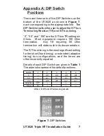
There are three sets of five DIP Switches on the
bottom of the UT3620 as shown in
Figure 7
,
each corresponding to the appropriate line.
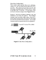
“0”, “50”, and “100” are the S/T bus TR settings in
Ohms. Most equipment requires 100 Ohm
termination. Any TE requiring 50 Ohm
termination will state such in its documentation.
The S/T bus timing is the most significant setting
for the short (fixed timing) or extended (adaptive
timing) bus configurations, and the terms are
often incorrectly equated.
Details of each DIP Switch are given in
Table 1
.
The asterisks represent the default positions.
The
DIP Switches allow the user to adjust the S/T bus
Terminating Resistor (TR) and S/T bus timing.
Setting
0
50
100
Adaptive
Fixed
1
---
---
---
Off*
On
2
Off
On
Off*
---
---
3
Off
On
Off*
---
---
4
Off
On
On*
---
---
5
Off
On
On*
---
---
7
Table 1. DIP Switch Position Assignments
Figure 7.
DIP Switches
UT3620 Triple NT1 Installation Guide
Summary of Contents for UT3620 Triple NT1
Page 1: ...UT3620 Triple NT1 Installation Guide ...
Page 2: ......
Page 23: ...NOTES 17 UT3620 Triple NT1 Installation Guide ...
Page 24: ...18 UT3620 NT1 Installation Guide Triple ...
Page 25: ...Wall Mounting Template 4 73 19 UT3620 Triple NT1 Installation Guide ...
Page 26: ......
Page 27: ......

