background image

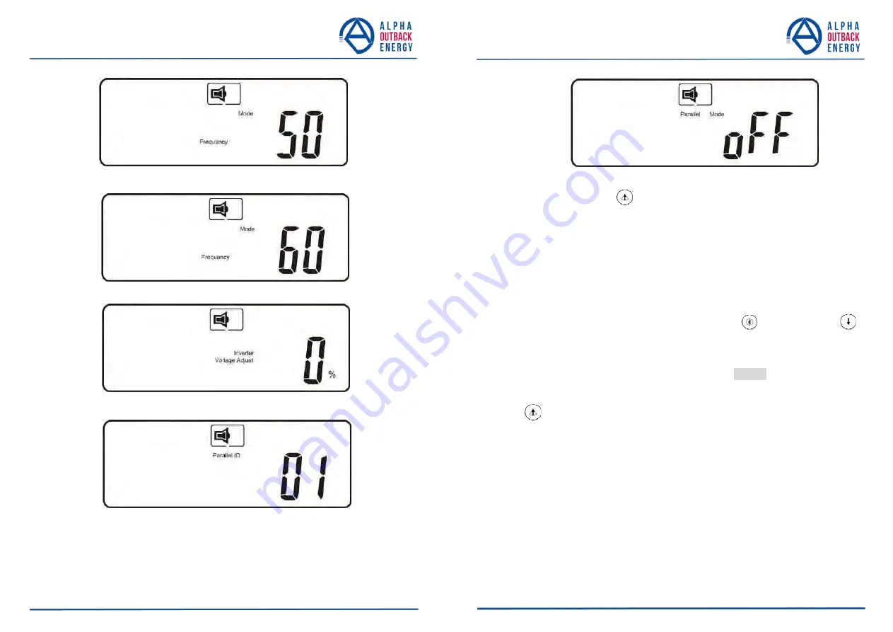
The parallel function is disabled. 

3.5.4.3.  Press the scroll up 

  key to execute special functions. The functions 

include buzzer ON (as in figure Q1), buzzer OFF (as in figure Q2, Alarm 

silence for UPS Warning), and self-test OFF (as in figure R1) or self-test 

ON (as in figure R2). The UPS will execute the battery test for ten 

seconds. If the self-test is successful it will display figure E1; otherwise, it 

will display figure E2 and an error message at the same time.) 

V3 

Page 

3

3

 to 

4

5

Page 

3

2

 to 

4

5

3.5.5.  UPS Default Settings and their alternatives 

3.5.5.1.  Make sure the UPS is not “On”. Press the On 

  and scroll down 

keys simultaneously for approximately three seconds. The buzzer will 

sound twice, and the LCD will display figure Q1, indicating that the UPS 

is in setting mode. 

3.5.5.2.  To scroll through the options refer to section 3.5.4.2. 

3.5.5.3.  Except for Buzzer (figures Q1 and Q2) and Self-test (figures R1 and R2) 

all of the other default settings may be changed by pressing the scroll up 

  key. 

3.5.5.4.  Figures S1 and S2 indicate the bypass input acceptable window. It 

follows the inverter output voltage. Please refer specification for the 

detail. 

3.5.5.5.  Figure T indicates the bypass frequency window of the Inverter Output. 

The acceptable setting values are ±3 Hz and ±1 Hz. 

3.5.5.6.  Figure U indicates the acceptable Inverter Output Voltage. Possible 


values are 200, 208, 220, 230, or 240 VAC. 

3.5.5.7.  Figures V1, V2, V3 and V4 indicate the operation modes of the UPS. 

Possible values are Online, Eco (Economical) mode, fixed 50 Hz 

Output, and fixed 60 Hz Output. 

The UPS is operating in “CVCF 50 Hz mode”. 

V4 

The UPS is operating in “CVCF 60 Hz mode”. 

Output Voltage Adjustment    (-3%, -2%, -1%, 0%, +1%, +2%, +3%) 

UPS position in parallel mode 

Summary of Contents for Continuity 10K

Page 1: ...Continuity 6K 10K USER MANUAL...

Page 2: ...5 3 Installation and Operation 16 3 1 Unpacking 16 3 2 Selecting Installation Position 17 3 3 Installation of Accessories Kit 18 3 4 Terminal Block Explanation 19 3 5 Installation and Operation 23 4 T...

Page 3: ...ondensing humidity 1 1 11 Do not install the UPS in direct sunlight Your warranty may be void if the batteries fail 1 1 12 Install the UPS indoors as it is not designed for installation outdoors 1 1 1...

Page 4: ...parts on top of batteries 5 Disconnect charging source prior to connecting or disconnecting battery terminals 6 Determine if battery is inadvertently grounded If inadvertently grounded remove source f...

Page 5: ...pass mode and vice versa 2 1 7 The fully digitalized control circuit built into the UPS allows upgrading the functionality of the UPS as well as reaching a high level of protection of the UPS Powerful...

Page 6: ...ry charging device k Internal Battery When AC abnormal it provide the backup power from the batteries l External Battery Bank To provide longer backup time by adding additional Battery bank m Inverter...

Page 7: ...hort Circuit 27 Er10 Inverter Over current Item Symbol Description 28 Er11 The UPS is overheated 29 Er12 UPS Output Overloading 30 Er14 Fan Error 31 Er15 Wrong Procedure to Enter Maintenance Mode 32 E...

Page 8: ...ndicates that the utility input voltage is outside the acceptable window Green LED indicates that Bypass Input is normal UPS ON Alarm Silence Go to previous page or change the setting of the UPS Confi...

Page 9: ...1 1 You may use optional interfaces cards for R2E RS 232 RSE RS 485 USE second USB DCE Dry Contact and SNMP However the R2E card RSE card and USE card must not be used simultaneously 2 4 1 2 The softw...

Page 10: ...y but not for moving UPS 3 2 Selecting Installation Position Install the UPS in a proper environment to minimize the possibility of damage to the UPS and to extend the life of the UPS Please follow th...

Page 11: ...e terminals for UPS Output G2 the terminal for UPS Output Ground Remarks 1 The maximum current for each terminal is 36 Arms for 6 kVA 65 Arms for 10 kVA 2 If the UPS is a SIM Single Input type only AC...

Page 12: ...module socket 3 Please refer to the specifications of input current output current and recommended conductors listed below a AC input and output minimum 75 C copper wire b Battery input Page 21 to 45...

Page 13: ...sure the utility voltage matches the input voltage window of the UPS 3 5 1 4 Connect the utility separately to the terminal blocks of the UPS Utility and Bypass inputs Switch on the power breaker of t...

Page 14: ...or error status will appear on the screen 3 5 1 9 Your start up operation of the UPS is complete now Make sure the UPS is plugged into the wall receptacle for charging at least 8 hours and the batteri...

Page 15: ...own the LCD will display figure C Voltage from Utility Input figure I1 Voltage from Bypass Input figure J Frequency from Utility Input figure K Frequency from Bypass Input figure L UPS Output Voltage...

Page 16: ...UPS battery numbers Page 29 to 45 Page 28 to 45 P UPS inner temperature 3 5 4 UPS Default Data and Special Function Execution 3 5 4 1 After the UPS completely starts up press the key to change the LC...

Page 17: ...r Output Voltage figure V1 UPS Operation Mode figure W Output Voltage Micro Tune Value figure X UPS Id figure Y Parallel function status R1 Self test is not On R2 Self test is On S1 Bypass Voltage is...

Page 18: ...in setting mode 3 5 5 2 To scroll through the options refer to section 3 5 4 2 3 5 5 3 Except for Buzzer figures Q1 and Q2 and Self test figures R1 and R2 all of the other default settings may be chan...

Page 19: ...d twice 3 5 6 2 4 Turn Off the Utility Input breaker 3 5 6 2 5 Even if the UPS lock problem is solved now consult with your local distributor to make sure that the error condition is resolved 3 5 7 Sh...

Page 20: ...36 to 45 Situation Check Items Solution red Fault LED Check the error code shown on the LCD 1 Check for proper battery connection then recharge the batteries for 8 hours to see whether the UPS provid...

Page 21: ...lt your local distributor for help Situation Check Items Solution Pin 1 UPS on Bypass mode Pin 2 Utility Abnormal Pin 3 Utility Normal Pin 4 Inverter On Pin 5 Battery Low Pin 6 Battery Bad or Abnormal...

Page 22: ...6 2 DCE Dry Contact C card 6 2 1 Please refer to the New Dry Contact Card English Installation Guide A5 192321002014002 Page 41 to 45 Page 40 to 45 6 3 Interface Card Installation...

Page 23: ...ly Battery Low Battery Bad Disconnect Overload Transferring with interruption UPS Fault Input Voltage Input Frequency Output Voltage Output Frequency Load Percentage Battery Voltage Inner Temperature...

Page 24: ...LCD Line Mode Backup Mode ECO Mode Bypass Supply Battery Low Battery Bad Disconnect Overload Transferring with interruption UPS Fault Input Voltage Input Frequency Output Voltage Output Frequency Loa...

Page 25: ...k energy com France and Benelux fbnl alpha outback energy com Spain spain alpha outback energy com Russia russia alpha outback energy com Africa africa alpha outback energy com Alpha and Outback Energ...

Reviews: