SNQ-60x0-320F Series Data Center Switch
Hardware Installation Guide
15
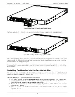
The figure below illustrates how the back panel will look with an AC power supply module properly installed.
Figure 5-8 Installing an AC Power Supply Module (After)
To remove the AC power supply module, remove the AC power cord and then press the clip to the left and pull the
lever backwards.
Installing a DC Power Supply Module
This section will assist administrators with the installation and replacement of DC power supply modules in this switch.
On the back panel of the switch, there are two power supply module slots. The input DC voltage requirement for the
DC power supply module is between
-40.5 VDC
to
-60 VDC
.
The figure below illustrates how to properly install a DC power supply module.
1.
It is important to make sure which
airflow direction
is used in this switch. Have a look at the fan modules
installed and make sure that the DC power supply module supports the same airflow direction. The airflow
direction can either be
front-to-back
or
back-to-front
airflow.
2.
Remove the power supply module slot’s protective cover by simply pulling the lever attach to it. The cover
should come off without any difficulty.
3.
Insert the DC power supply module, without a DC power cord supplying power, into the power supply module
slot. Make sure that the DC power supply module is inserted all the way until the clip clicks into place.
4.
Connect one end of the DC power cord, included in the package, to a DC power source and insert the other
end of the power cord to the DC power port connectors of the DC power supply module.
Warning:
Make sure that the voltage requirement and connection polarity (positive and negative) is
correct before connecting the power cord to the power port connectors of the power supply
module to avoid any damage.


