background image

ONLINE MONITORING

ONLINE MONITORING

26

27

Online Monitoring

08

8.1 Register

Figure 8-1 Monitoring login interface

Figure 8-2 Register interface

Open the portal: www.alphaess.com.

You have to create a new account on our web server for the normal monitoring. 
So please use the following steps:

Enter the username and password, then click “Login” to jump to the home page. There 
will be a prompt after a failed login.

Users who haven't yet registered need to click “Register” to visit the registration page: (as 

shown below)

Boxes followed by a “*” mark must be filled, 

and the contents you fill must consist with 

the facts. Registered users come in 2 types: 

end users and installers. Please choose 

between them according to the actual 

situation. Then you can check whether you 

need auto upgrade or not according to your 

own situation. Then Click “SIGN UP NOW” to 

go to the login page.

More detailed information can be obtained in 

Online Monitoring Web server installation 

Manual.

Register

*

 E-mail

*

 Contact Number

*

 Username

*

  Country / Region

City/Town

Province/State

*

 Password

*

 Confirm Password

*

  Language

*

  E-mail

*

  Contact Person

*

 Time Zone

Address

*

 Zip Code

*

 Contact Number

User Type

*

 S/N

Sign up Now

Back

Imprint Privacy Policy

      Whether to allow automatic update (the automatic upgrade function is to actively update the latest push program 
to improve the use of the device when the system is online.)

Agree to the above terms 

Terms and Conditions

8.2 Registering License

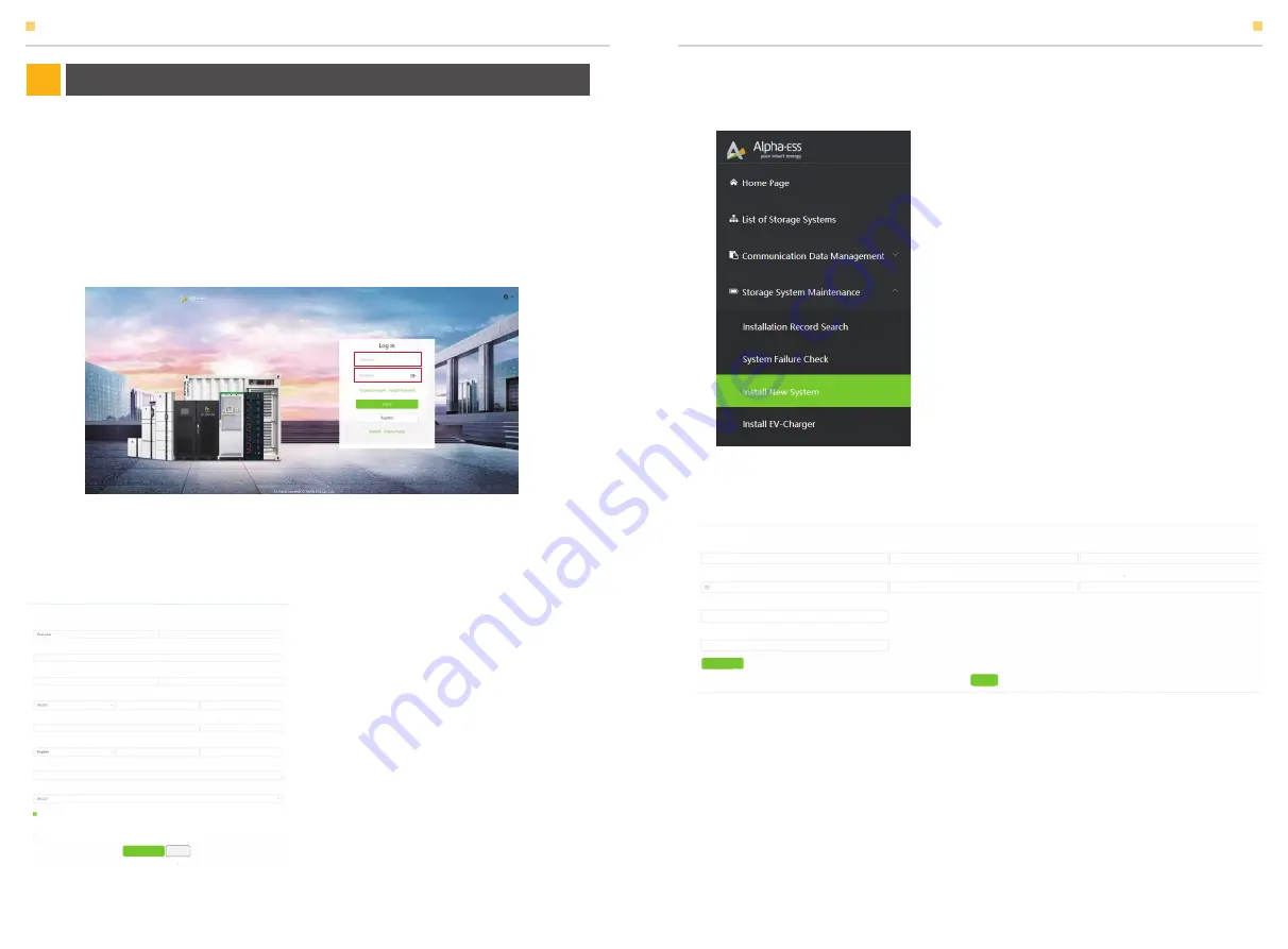
Figure 8-3 Menu for installer

Figure 8-4 System registering interface

Click Install new system to register the 

license No.

Input S/N, Check Code, License No., Date, Name, and Contact No. to complete the 

registering process.

Install New System

S/N

*

Create Time

Address

Remark

*

*

*

*

Check Code

Customer Full Name

*

*

License

*

Contact Number

*

Attachment

Save

Summary of Contents for Storion-T100

Page 1: ...pha ess de www alpha ess de Paul Ehrlich Straße 1a 63225 Langen Alpha ESS Australia Pty Ltd 61 1300 968 933 australia alpha ess com www alpha ess com au Unit 1 2 Ralph Street Alexandria NSW 2015 Alpha ESS Italy S r l 39 599 239 50 info alpha ess it www alpha ess it Via Loda 17 41013 Castelfranco Emilia MO Alpha ESS Korea Co Ltd 82 64 721 2004 korea alpha ess com 2F 19 4 Nohyeong 11 gil Jeju si Jej...

Page 2: ...0 4 1 Check Before Operation 4 2 Power on Procedures 4 3 Power off Procedures 2 1 Keep the Manual 2 2 Operator Requirements 2 3 Protection of Warning Sign 2 4 Setting of Warning Sign for Safety 2 5 Live Line Measurement 2 6 Measuring Equipment 2 7 Electrostatic Prevention 2 8 Moisture Prevention 2 9 Operation after Power Failure 2 10 Minimum Personal Protective Equipment 17 EMS OPERATION 05 This ma...

Page 3: ...tion 01 This manual applies for Storion T50 T100 Li ion battery energy storage system mainly includes 3 System installation Introduces the installation of T50 T100 including precautions 4 Routine maintenance Introduces items in maintenance of T50 T100 Li ion battery energy storage system including attentions 5 Troubleshooting Introduces the faults of T50 T100 Li ion battery energy storage system c...

Page 4: ...tteries connected in series parallel in the pack with a battery management system BMS in which accesses to DC side of a bidirectional converter 2 1 Keep the Manual 2 2 Operator Requirements This manual contains important information about operating the system Before operating please read it very carefully The PCS should be operated in strict accordance with the description in the manual in case of...

Page 5: ...than 95 Repairing or maintaining activities in wet conditions should be avoided or limited 2 8 Moisture Prevention 2 9 Operation after Power Failure The battery system belongs to energy storage system which maintains fatal high voltage even when the DC side is disconnected Therefore touching of the battery output is strictly prohibited The PCS maintains fatal voltage even when both the DC or AC si...

Page 6: ...of the inverter in this LCD screen B C D F G H I E F H E G ENT Main Interface displays the system working status and information including Power Total AC output power Pload Total load power Battery State of charge SOC offGridMode Current working state of the equipment including alarm type In the Main interface press ENT key to enter the Menu Power 0W Pload 00 0kWh Battery offGridMode Setting Informa...

Page 7: ...ibrate SOC Reserved Set the installed PV capacity of the grid con nected inverter if the PV inverter is controlla ble it is the total rated power of the PV inverter Set the installed PV capacity of the energy storage machine Setting Function Grid UPS System System Mode Pmeteroffset PmeterMax Peak Shave LowerLimit Enable Offset Start Time 1 End Time 1 Start Time 2 End Time 2 Peak ShaveEN UpperLimit S...

Page 8: ...Work Mode Charge End Time 1 Charge Start Time 2 Charge Start Time 2 Set the charging end time of the first stage Set the charging start time of the second stage Set the charging start time of the second stage Set the upper limit of charging SOC Charge cut SOC DisCharge Start Time 1 DisCharge End Time 1 Set the discharge time of the first stage Set the first stage to stop the discharge time Set the lo...

Page 9: ...o re power after setting Server IP Server Port Client IP English Deutsch Local Remote CtrlMode Protocol Scheduling device address Scheduling timeout 0 means unlimited time for EMS connection If the timeout is not set as 0 EMS will not be connected when the time is out Dev_addr EMS_timeout ComMode ModbusRTU ModbusTCP MSID No used Clear inverter power statistics Clear the energy statistics of the me...

Page 10: ...tch turn it on C After the power is on the LED on the batteries and HV900112 starts flashing E If the battery status is correct turn on the battery and PV switches of the system by pushing up the switch handles The green indicator of the system starts flashing After 10 seconds the red indicator is on F Turn on the load switch and grid switch by pushing up switch handles D After waiting for about 2 m...

Page 11: ...EMS Setting Function CT Meter Enable NO G Check the system mode is DC EMS Setting Function System Mode DC H Check the maximum charge power of system EMS Setting Function System Mode ChargePower Power 50kW 100kW I Set up the PV storage capacity EMS Setting Function Solar Enable Storage Cap J Set up the generator parameters a Open the generator EMS Setting Function Generator Enable YES b Check the g...

Page 12: ... Enable YES G Check the meter ratio is correct EMS Setting Function CT Meter Ratio 80 H Check the system mode EMS Setting Function System Mode DC AC Hybrid I Check the maximum charge power of system EMS Setting Function System Mode ChargePower Power 50kW 100kW J Set up the discharge cut SOC of the system EMS Setting Function System Mode DischargeCutSOC 11 K Set up the PV storage capacity EMS Setti...

Page 13: ...tion System Mode Discharge End Time 1 J Set up the second discharge start time EMS Setting Function System Mode Discharge Start Time 2 K Set up the second discharge end time EMS Setting Function System Mode Discharge End Time 2 L Set up the discharge cut SOC of the system EMS Setting Function System Mode DischargeCutSOC 11 D E F Plug Down button View the power in the viewing interface move right i...

Page 14: ...ratio METER INSTRUCTION METER INSTRUCTION 22 23 1 Press SET and the screen shows PASS 2 Press ENT and the screen shows 0000 3 Input 0001 as the password and press ENT 4 Set the parameters 5 After settings press SET and the screen shows SAVE 6 Select YES and press ENT to save the settings Examples of display interface Table 4 Partial display interface diagram Current forward active energy 12 34kWh ...

Page 15: ...s SET to enter SAVE press Enter to select Yes to save H The setting is over 001 EMERGENCY STOP INSTALLATION 24 25 Emergency Stop 07 When the energy storage system is abnormal you can press the emergency stop button EPO on the cabinet door and then follow the step A to E in 4 3 to power it off In order to prevent personal casualty if you want to repair or open the machine after power off please measu...

Page 16: ...ccording to your own situation Then Click SIGN UP NOW to go to the login page More detailed information can be obtained in Online Monitoring Web server installation Manual Register E mail Contact Number Username Country Region City Town Province State Password Confirm Password Language E mail Contact Person Time Zone Address Zip Code Contact Number User Type S N Sign up Now Back Imprint Privacy Pol...

Page 17: ...tain the equipment by observing the status of the equipment indicator lights and software monitoring information Check items Check content Time Notes Indicator light 1 Battery Inspection requirements Once 6 months EMS display There is nothing wrong with the EMS display when the system is operating normally The fault light goes out and the interface displays On Grid Mode Flashing green light Once 6...

Page 18: ...er outage inspection maintenance work etc Check items Check content Time Notes 1 Battery Inspection requirements Check whether the wiring harness between batteries is tightly locked Connection between batteries Connection between the battery and highvoltage control box Once 6 months Check whether the wiring harness between the Battery and the highvoltage control box is locked All locked not loose ...

Page 19: ...ould be in good electrical connection with the surface of the battery rack and the grounding point use a multimeter to test the conduction state Check whether the ground wire of the battery rack is well connected Once 6 months Once 6 months Once 6 months Check whether the appearance of all batteries and high voltage control boxes in the system is normal The battery rack is well fixed The battery ra...

Page 20: ...wer off Check if the inverter is damaged or deformed Operating status Environment Check whether the inverter makes abnormal noises during operation Check whether all components are normal during the operation of the inverter Check the temperature of the inverter shell and use a thermal imager to monitor the temperature of the system Check whether the air inlet outlet is normal Check the humidity an...

Page 21: ...l positive and the ground and the total negative and the ground of the junction cabinet should be 5MΩ Once 6 months Once 6 months Once 6 months Once 6 months Once 6 months Once 6 months Whether the grounding resistance of the battery high voltage box and cabinet is within a reasonable range PCS live part screws collection wiring harness communication wiring harness inspection Use the multimeter to...

Page 22: ...e of the loads to check if the fault is eliminated If the problem is not resolved stop any operation on the system and contact AlphaESS customer service Pole Ov Temp Pole over temperature fault Shut down the system for about 2 hours then restart the system to see if the fault is eliminated If the problem is not resolved please contact AlphaESS customer service Cell Ov Volt Cell over volt fault Res...

Page 23: ...he problem is not resolved please contact AlphaESS customer service PV Meter Lost PV Meter Lost Check if the communication cable between the PV side meter and the GRID meter is connected If the problem is not resolved please contact AlphaESS customer service SD Lost SD Lost Restart the system to check if the fault is eliminated If the problem is not resolved please contact AlphaESS customer servic...

Page 24: ... phase loss in the AC input of the inverter If there is a phase loss please power off and reconnect the cable If the problem is not resolved please contact AlphaESS customer service off_grid_UPLF DC AC subsystem off grid voltage phase lost Fault Check if there is phase loss in the AC input of the inverter If there is a phase loss please power off and reconnect the cable If the problem is not resolved ...

Reviews: