background image

3

Summary

Commissioning Document

Handling and Safety Instructions

I/ What’s in the box

II/ Mounting the SolShare  


A. Installation site selection 


B. Installation 

III/ Electrical connection


A. Input / Output connections


B. Output connection to main switchboard


C. Running current transformer tails


D. Current transformers to SolShare connections 


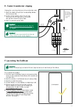
E. Current transformer clipping 


F. Launch the SolShare

Appendix

Technical Specifications

p05

p06

p07

p09

p09

p10

p11

p11

p15

p16

p16

p17

p17

p18

p21

Summary of Contents for SolShare 100

Page 1: ...1 SolShare Installation Manual...

Page 2: ...itten permission of Allume Energy and end users may not divulge the information contained herein or use this manual for purposes other than those strictly connected with correct use of the equipment A...

Page 3: ...n B Installation III Electrical connection A Input Output connections B Output connection to main switchboard C Running current transformer tails D Current transformers to SolShare connections E Curre...

Page 4: ...the past As a result please follow the guidelines in this manual carefully Your system is designed to meet all United States conditions regulations and codes This guide provides the general instructio...

Page 5: ...on Serial Number Installer name Company SolShare Connection Unit Connected eg Apt 1 Unit B Common light power No connection Unit number 1 L1 2 L2 3 L1 4 L2 5 L1 6 L2 7 L1 8 L2 9 L1 10 L2 Unit Connecti...

Page 6: ...elf with the symbols and their meaning before installing or operating the system Important xxxxx xxxx xxxx xxx xxxx xx xxxx xxx xxxx Important xxxxx xxxx xxxx xxx xxxx xx xxxx xxx xxxx Warning xxxxx x...

Page 7: ...ease contact your dealer immediately Carefully check that all of the components have been supplied If anything is missing contact your dealer I What s in the box Mounting bracket Fastener Split curren...

Page 8: ...ly units The SolShare takes a single split phase input from a grid connected solar inverter s and connects to each participating unit on a single line L1 or L2 to the load side of their Unit Main Swit...

Page 9: ...serve and operate location 90 Mounted Vertically 90 Mounted Vertically 1200 mm To minimise cabling required the SolShare should be mounted as close to the main switchboard tenancy isolator board as po...

Page 10: ...s below to mount the brackets and enclosure 1 Firmly secure the mounting brackets to the chosen wall for installation Allume Energy recommend using the provided fasteners to attach the brackets into a...

Page 11: ...rds and away from you then allow to slide down back into place A Input Output Connections 1 Lift up cover to reveal the lower section of the box where the electrical connections are made INPUT SOLAR O...

Page 12: ...Main Switch 4 Run output conduits from out glands to Unit Solar Circuit Breakers TO METER PANEL FROM INVERTER PRE EXISTING EARTH CONNECTIONS TO ENCLOSURE Important The Unit Solar Circuit Breakers can...

Page 13: ...length 14mm Tightening torque 18 lb in 2Nm Earth Connection Please refer to Appendix p19 for Conductor Specification options 1 Run input earth from inverter and connect to the SolShare s earth bar as...

Page 14: ...output power cables to appropriate length to reach from SolShare output to Unit Solar Circuit Breakers Label both ends of these cables with the unit apmt number 3 Run cables between SolShare and Unit...

Page 15: ...ure clear labeling in the main switchboard of the location of solar circuit breakers The outputs from the solar must be wired to the solar circuit breakers The outputs of the solar circuit breakers mu...

Page 16: ...s of the red phase 3 Repeat steps 1 2 for white and blue phase connector blocks 4 Plug each CT connector block into the corresponding socket of the SolShare Important Make sure colours and orientation...

Page 17: ...re Fasten shut by replacing the 4 screws on the underside of the SolShare that were removed in section III A 1 2 Switch on all solar circuit breakers and unit main switches 3 Switch on inverter main s...

Page 18: ...orresponds to the solar input Parameter Specification Panel thickness 4 4 5mm CT Hole Diameter 33mm Solar Input Output hole diameter 32mm Flammability rating minimum UL94 HB Temperature rating minimum...

Page 19: ...OF 55 14 0 COMPRESSION CONNECTORS WITH 1 2 STUD HOLE MAX TONGUE WIDTH OF 44 4 0 BARE COPPER WIRE FROM 14 AWG TO 4 AWG Appendix B Ground Bar Connection Diagram 1 Tightening Torque IN LBS N m Conductor...

Page 20: ...gths Bent tongue and narrow tongue options are available Diagram 3 Appendix C Terminal Block Connection Connection data Metric US Tightening Torque 2 Nm 18 lb in Conductor Cross Section Stranded min 4...

Page 21: ...d between the inverter and the building s meter panel It requires no change to their existing smart meter infrastructure or the utility s billing system and is designed to make installation as simple...

Page 22: ...C Max nominal current per phase 100 A Voltage Range phase to neutral 100 260 VAC Voltage Drop I is nominal current 0 9 002 I Mains frequency range 50 60 Hz Overcurrent rating 30 kA Max input at 240V...

Page 23: ...This manual is intended for installations in the USA Specifications are subject to changes without advanced notification Allume Energy Ltd www allumeenergy com au info allumeenergy com 61 394 270 005...

Reviews: