background image

10 

SAFETY 

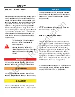
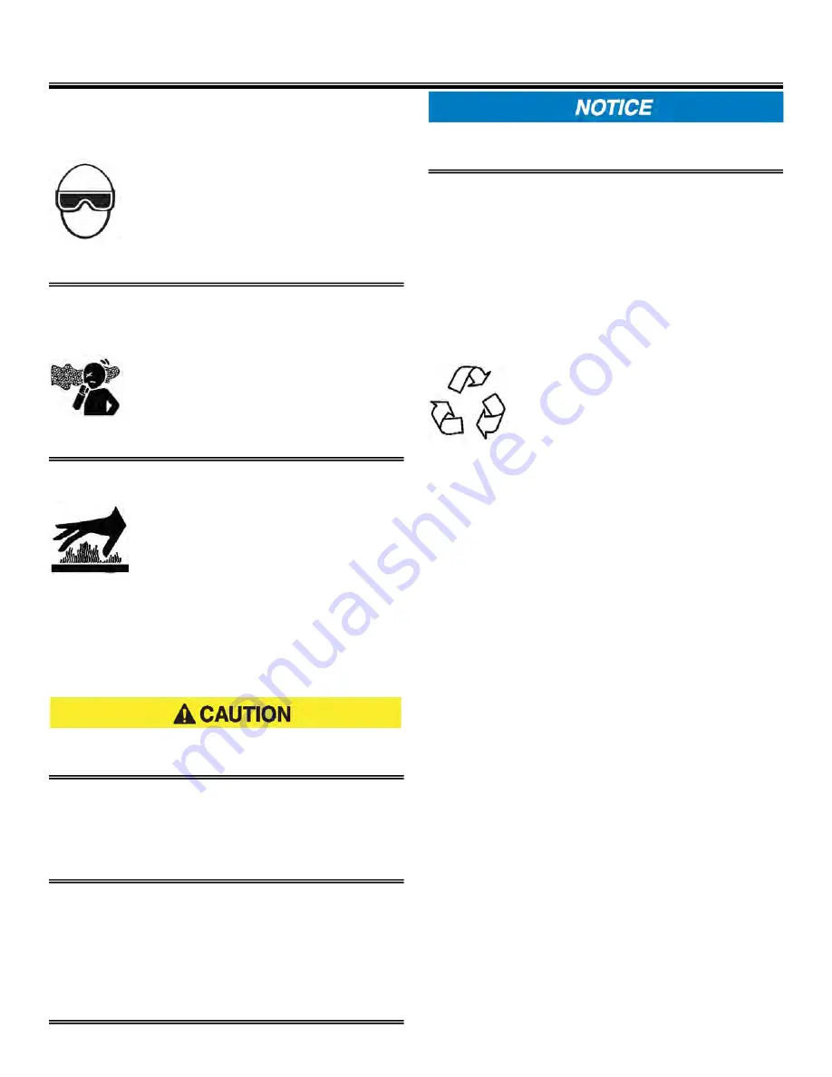
FLYING OBJECT HAZARD 



Always wear eye protection when 
cleaning the equipment with   
compressed air or high pressure 
water. Dust, flying debris,       
compressed air, pressurized    
water or steam may injure your 
eyes. 

COOLANT HAZARD 



Wear eye protection and rubber 
gloves when handling engine 
coolant. If contact with the eyes or 
skin should occur, flush eyes and 
wash immediately with clean    
water. 

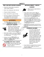
BURN HAZARD 




light fixtures and some of the     
engine surfaces become very hot 
during operation and shortly after 
shutdown. 



Keep hands and other body parts away from 
hot engine surfaces. 



Handle hot components, such as light      
fixtures, with heat resistant gloves. 

The safety messages that follow have     

CAUTION level hazards. 

TOOL HAZARD 



Always use tools appropriate for the task at 
hand and use the correct size tool for     
loosening or tightening equipment parts. 

SLIP HAZARD 



Immediately clean up any spilled liquid on 
the shop floor. 



Clean up accumulated dirt and debris on the 
shop floor at the end of each shift. 

The safety statements that follow have       

NOTICE level . 



Any part which is found defective as a result 
of inspection or any part whose measured 
value does not satisfy the standard or limit 
MUST be replaced. 



Always tighten components to the specified 
torque. Loose parts can cause equipment 
damage or cause it to operate improperly. 



Only use replacement parts specified. 
Other replacement parts may effect       
warranty coverage. 



Clean all accumulated dirt and debris away 
from the body of the equipment and its  
components before you inspect the    
equipment or perform preventative      
maintenance procedures or repairs. Oper-
ating equipment with accumulated dirt and 
debris will cause premature wear of    
equipment components.  



Never dispose of hazardous materials by 
dumping them into a sewer, on the ground, 
or into groundwater or waterways. 



Retrieve any tools or parts that may have 
dropped inside of the equipment to avoid 
improper equipment operation. 



Follow the guidelines of the EPA 
or other governmental agencies 
for the proper disposal of       
hazardous materials such as   
engine oil, diesel fuel and engine 
coolant.  



If any alert indicator illuminates during      
equipment operation, stop the engine           
immediately. Determine the cause and re-
pair the problem before continuing to oper-
ate the equipment. 

Not 

for 

Reproduction

Summary of Contents for MAXI-LITE AS3000

Page 1: ...R S MANUAL ALLMAND BROTHERS INC P O BOX 888 HOLDREGE NE 68949 PHONE 308 995 4495 1 800 562 1373 ALLMAND FAX 308 995 5887 ALLMAND PARTS DEPT FAX 308 995 4883 WWW allmand com PART NO 103565 REVISED JANU...

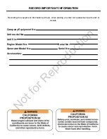
Page 2: ...the equipment information will help when placing an order for replacement parts and or decals Company Equipment No Unit model No Unit Vin Engine Model No Serial No Generator Model No Serial No Accesso...

Page 3: ...WN 15 TOWER LIGHTS REMOVAL FOR TRAILERING TRANSPORTING OPTIONAL 16 TRAILER TOWING 16 TRAILER COMPONENT IDENTIFICATION 16 TOWING VEHICLE AND HITCH CONSIDERATIONS 17 18 LIFTING THE LIGHT TOWER 18 TRANSP...

Page 4: ...2 BATTERY DISCONNECT SWITCH 32 AUTOMATIC ENGINE SHUTDOWN SYSTEM 32 TOWER AND LIGHT OPERATION VERTICAL 32 TOWER AND LIGHT OPERATION LAYDOWN 32 LIGHTBAR AND LIGHT FIXTURE ADJUSTMENT VERTICAL 33 LIGHTBAR...

Page 5: ...41 FRAME 41 GREASE POINTS 42 TRAILER WHEELS AND TIRES 42 WHEEL BREARINGS 42 43 TRAILER LIGHTING 43 LONG TERM STORAGE 43 CLEANING 44 CLEANING AND DRAINING THE TRAILER BILGE 44 TROUBLESHOOTING 45 TROUBL...

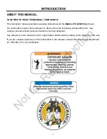
Page 6: ...al is in effect at the time of printing Allmand Bros Inc may change contents without notice and without incurring obligation Any reference in this manual to left or right shall be determined by lookin...

Page 7: ...symbol appears with most safety statements It means attention become alert your safety is in volved Read and abide by the mes sage that follows the safety alert symbol Indicates a situation which can...

Page 8: ...n effect the safe operation of the equipment EXPOSURE HAZARD Always wear personal protec tive equipment including appropriate clothing gloves work shoes and eye and hearing protection as required by t...

Page 9: ...vice while it is operating remove all jewelry tie back long hair and keep hands other body parts and clothing away from moving rotating parts Verify that all guards and covers are attached properly to...

Page 10: ...rt which is found defective as a result of inspection or any part whose measured value does not satisfy the standard or limit MUST be replaced Always tighten components to the specified torque Loose p...

Page 11: ...Refer to these representations of the safety warning decals used on the MAXI LITE AS3000 light tower to insure correct ordering if replacement becomes necessary SAFETY LABELS N o t f o r R e p r o d u...

Page 12: ...itch assembly and safety chains Check the outriggers and jacks to make sure they operate properly Inspect the light assemblies for damage and test for proper operation Inspect the electrical wiring fo...

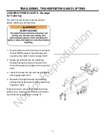
Page 13: ...bilizer jack and rotate into trailering position horizontal with outrigger bar 8 Retract each outrigger bar and secure in the stowed position with latch pin 4 Secure the light cords into the hook on t...

Page 14: ...retracted position 3 Rotate the light bar into the trailering trans porting park position inline with the trailer and engage the park pin by twisting the park pin ring until the plunger is released an...

Page 15: ...2 Rotate the light bar into the trailering transporting park position inline with the front of the trailer and tighten the tower lock knob 3 Lower the tower into the rear tower support and engage tow...

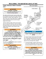
Page 16: ...for theft protection Tongue Jack Ball Hitch Coupler Safety Chains Trailer Component Identification 1 Ensure lights are off and tower is lowered to the full DOWN position See Raising and Lowering the...

Page 17: ...the trailer Before trailering always check your vehicle owners manual for maximum towing trailering load specifications and maximum gross vehicle weight specifications that include the fully loaded t...

Page 18: ...with enough slack to permit free turning 3 Connect the 7 pin light connector from the trailers harness to the vehicles harness TRAILERING TRANSPORTING AND LIFTING 7 pin Trailer Light Harness Connecto...

Page 19: ...TRAILER When transporting the light tower trailer on a truck or a trailer always secure the unit using properly rated tie down chains or straps con necting the light tower frame using tie down loops t...

Page 20: ...ASSEMBLY LEFT FUEL TANK AND CONTROL ACCESS DOOR HYDRAULIC LIGHT TOWER FRONT STABI LIZER JACK FRONT OUTRIGGER TRAILER TONGUE JACK COUPLER PARK BRAKE STEP PLATE Hydraulic Only SAFTEY CHAINS BALLAST ACCE...

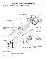
Page 21: ...SEMBLY CORD REEL LAYDOWN LIGHT TOWER FORKLIFT POCKETS LEFT FUEL TANK AND CONTROL ACCESS DOOR FRONT STABILIZER JACK FRONT OUTRIGGER BALLAST ACCESS PANEL COUPLER SAFETY CHAINS TRAILER TONGUE JACK PARK B...

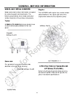
Page 22: ...he rear panel TRAILER SERIAL PLATE STAMPED SERIAL PLATE SPECIFICATIONS STANDARD AND OPTIONAL FEATURES Generator The generator has a serial number plate attached to the side of the housing MARATHON Eng...

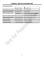
Page 23: ...outriggers retracted 1 9 m 74 in 1 95 m 76 ft 3 4 in Manual Winch 1 87 m 74 in Electric Winch Width outriggers extended 3 91 m 12 ft 10 in 3 91 m 12 ft 10 in Length w o Fixtures 3 14 m 10 ft 4 in 4 1...

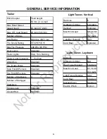
Page 24: ...lift Pockets Standard Top Forklift Pockets Standard Number of Stablizers 4 Number of Outrigger Stabilizers 2 Tongue Jack Standard Ground Rod Standard Trailer Light Tower Laydown Light Tower Vertical S...

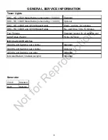
Page 25: ...D 1000W and 1205W Metal Halide Re start time 10 to 15 minutes Four Fixtures Standard sealed for all weather use Light Fixture Weight 15 lbs 6 75 kg Indivdual Light Switches 1000W Light Switch 2 per 4...

Page 26: ...p Oil Filteration Cartridge Type Cooling System Pressurized radiator forced circulation with water pump Low Oil Pressure Engine Shutdown High Engine Standard Tempurature Shutdown Glow Plug Cold Start...

Page 27: ...ng Pad Engine Block Heater Sound Attenuation package Four or Six Metal Halide or High Pressure Sodium Lamps 5 000 6 000 or 7 000 Watts Total 7 Blade RV Taillight Connector 189 L 50 gal Bulldog Hitch b...

Page 28: ...lat and level Wind The light tower will remain operational in sus tained winds up to 92 km h 57 mph when properly positioned on firm level ground with the outriggers and jacks properly positioned and...

Page 29: ...draulic fluid levels if equipped Check to make sure the Light Tower Operator s Manual Engine Operator s Manual and Generator Operator s Manual are with the equipment Physically inspect the machine for...

Page 30: ...the ground rod fully into the ground using a hammer Attach the supplied cable to the rod and then attach the cable to the ground lug on the unit Make sure the cable connections are tightened OUTRIGGE...

Page 31: ...ar may clash resulting in damage to the starter or flywheel ring gear Stopping the Engine The engine stopping procedure may differ depending on the engine model Refer to your Engine Operator s Manual...

Page 32: ...y move the fuel control to the shutoff position TOWER AND LIGHT OPERATION LAYDOWN Before operating the tower lights review Safety on page 7 The laydown light tower is raised and lowered by a manual wi...

Page 33: ...ed working position PARK PIN Cap Plug GRASP THE LIGHT HERE TO ADJUST Light Bar and Light Fixture Adjustment Vertical Lights Work Site Adjustment The light bar and light fixtures must be adjusted to th...

Page 34: ...nd Light Fixture Adjustment Laydown Lights Work Site Adjustment The light bar and light fixtures must be adjusted to the desired work angle before raising the light tower With The Light tower fully lo...

Page 35: ...owers the mast from horizontal towing position to the vertical position and back The second winch mounted on the tower extends and retracts the telescoping sections Before raising the light tower visu...

Page 36: ...king knob 3 Operate hand crank winch on tower counterclockwise to lower the lights to the lowest vertical position 4 Operate lower hand crank winch on the left side of the trailer clockwise to take up...

Page 37: ...the trailer Retighten knob 4 Push toggle switch to the DOWN position to lower the light to the lowest vertical position until the safety latch clicks 5 Push toggle switch to the UP position to lessen...

Page 38: ...rolled and protected by four breaker switches located on the light control panel LIGHT BREAKER SWITCHES SHUTDOWN PROCEDURE Shutdown When shutting down the light tower perform the following procedures...

Page 39: ...ding Engine Oil ELECTRICAL SYSTEM Refer to the Generator Operator s Manual for all general scheduled maintenance procedures Ballast Panel The ballast panel is located on the left front side of the lig...

Page 40: ...HYDRAULIC PUMP Hydraulic Oil Specification Priming the Hydraulic Pump The ports are marked on the hydraulic power unit casting UP and DN When facing the power unit with the motor up plug the right ha...

Page 41: ...riage for wear and damage and replace as needed 4 Inspect the outrigger bars front and rear stabilizer jacks and locking mechanisms for proper operation and wear and damage and replace as needed 5 Ins...

Page 42: ...service may be required under extremely dust or damp operating conditions The best protection against failure is to keep the wheel bearings clean and fully lubricated When replacing or repacking whee...

Page 43: ...o the full DOWN position 2 Make any repairs necessary to ensure the equipment is fully functional upon returning the unit back into commission 3 Clean and wash the frame and body panels Apply an antic...

Page 44: ...ith a damp cloth or sponge Inspect and clean all engine linkages so they operate properly Cleaning and Draining the Trailer Bilge The Allmand MAXI LITE AS3000 light tower trailers have a fuel containm...

Page 45: ...sformer has failed ONE OR MORE 6 Plug and socket at light bar not securely pushed together and locked LIGHTS 7 A loose connection in the back of the lamp socket in the lamp holder 8 If the lamps have...

Page 46: ...46 MAINTENANCE RECORD DATE SERVICE DESCRIPTION SERVICED BY N o t f o r R e p r o d u c t i o n...

Page 47: ...47 SCHEMATICS N o t f o r R e p r o d u c t i o n...

Page 48: ...48 SCHEMATICS N o t f o r R e p r o d u c t i o n...

Page 49: ...49 SCHEMATICS N o t f o r R e p r o d u c t i o n...

Page 50: ...50 SCHEMATICS N o t f o r R e p r o d u c t i o n...

Page 51: ...51 SCHEMATICS N o t f o r R e p r o d u c t i o n...

Page 52: ...52 WARRANTY N o t f o r R e p r o d u c t i o n...

Page 53: ...53 WARRANTY N o t f o r R e p r o d u c t i o n...

Page 54: ...EAR LIMITED 5000 HOURS ADVANCE BALLAST TWO 2 YEAR LIMITED MARATHON ONE 1 YEAR LIMITED MECC ALTE ONE 1 YEAR LIMITED STAMFORD ONE 1 YEAR LIMITED ATHLON ONE 1 YEAR LIMITED LIGHT TOWER ASSEMBLY TEN 10 YEA...

Reviews: