Chapter 4: Installing the Switch on a Wall
74
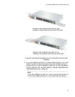
the front panel is on the left. Figure 31 shows the recommended position
of the device when the front panel is on the right.
Figure 30. Minimum Wall Area Dimensions for the Switch When the Front
Panel is on the Left
Figure 31. Minimum Wall Area Dimensions for the Switch When the Front
Panel is on the Right
Summary of Contents for AT-x310-26FP
Page 10: ...Tables 10 ...
Page 14: ...Preface 14 ...
Page 46: ...Chapter 1 Overview 46 ...
Page 56: ...Chapter 2 Beginning the Installation 56 ...
Page 92: ...Chapter 5 Cabling the Networking Ports 92 ...

