Chapter 4: AT-MCF2000M Management Module
58
Section I: Features
Front Panel
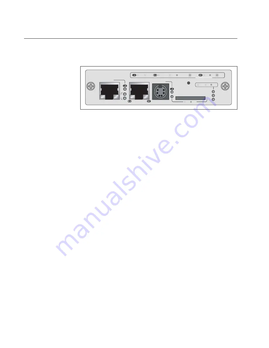
Figure 25 illustrates the front panel of the AT-MCF2000M Management
Module.
Figure 25. Front Panel of the AT-MCF2000M Management Module
The components on the front panel are described here:
❒
Stack port -This port is used to connect multiple chassis together so
they can be managed from one management module. For further
information, refer to Chapter 5, “AT-MCF2000S Stacking Module” on
page 73.
❒
10/100/1000Base-T Management Port - This is a standard Ethernet,
Fast Ethernet, and Gigabit Ethernet port. The module uses this port for
management functions that require communications with your
network, like remote (in-band) management from a Telnet or Secure
Shell (SSH) client and file transfers to or from a TFTP server. For
further information, refer to “10/100/1000Base-T Management Port” on
page 59.
❒
RS-232 Terminal port - You use this port for local (out-of-band)
management of the chassis. For further information, refer to “RS-232
Terminal Port” on page 61.
❒
Reset button - This button is used to perform a soft reset of the
module. It initializes the AT-S97 Management Software. For further
information, refer to “Reset Button” on page 63.
❒
SD slot - This slot is for a secure digital memory card for storing or
transferring configuration files. For further information, refer to “SD
Slot” on page 65.
AT-MCF2000M
STACK
MANAGEMENT
TERMINAL
10/100/1000BASE-T
RS-232
RESET
SD
RDY
BUSY
MASTER
POWER
BOOT
RDY
FAULT
1000 LINK
ACT
10/100 LINK
ACT
FDX
HDX
COL
LINK
ACT
PORT ACTIVITY
1421
SYSTEM
ID
31
0
Summary of Contents for AT-MCF2000
Page 8: ...Contents 8...
Page 12: ...Tables 12...
Page 18: ...Preface 18...
Page 20: ...20 Section I Features...
Page 26: ...Chapter 1 AT MCF2000 Multi channel Media Converter Series 26 Section I Features...
Page 54: ...Chapter 3 AT MCF2012LC AT MCF2012LC 1 and AT MCF2032SP Modules 54 Section I Features...
Page 72: ...Chapter 4 AT MCF2000M Management Module 72 Section I Features...
Page 84: ...Chapter 5 AT MCF2000S Stacking Module 84 Section I Features...
Page 86: ...86 Section II Installation...
Page 90: ...Chapter 6 Reviewing the Safety Precautions 90 Section II Installation...
Page 92: ...Chapter 7 Selecting a Location 92 Section II Installation...
Page 96: ...Chapter 8 Unpacking the AT MCF2000 or AT MCF2300 Chassis 96 Section II Installation...
Page 98: ...Chapter 9 Removing the Rubber Feet 98 Section II Installation...
Page 106: ...Chapter 11 Installing the AT MCF2KFAN Module 106 Section II Installation...
Page 110: ...Chapter 12 Installing a Media Converter Module 110 Section II Installation...
Page 122: ...Chapter 15 Installing the Chassis in an Equipment Rack 122 Section II Installation...
Page 128: ...Chapter 17 Installing the SFP Modules in the AT MCF2032SP Module 128 Section II Installation...
Page 130: ...Chapter 18 Cabling the Ports on the Media Converter Module 130 Section II Installation...
Page 134: ...Chapter 19 Cabling the AT MCF2000M and AT MCF2000S Modules 134 Section II Installation...
Page 138: ...Chapter 20 Powering on the Chassis 138 Section II Installation...
Page 156: ...Chapter 23 Troubleshooting the Modules 156 Section II Installation...
Page 186: ...Appendix C Cleaning Fiber Optic Connectors 186...
Page 190: ...Index 190...


