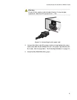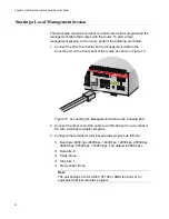
Installation Guide for AT-AR3050S, AT-AR4050S Routers
15
Unpacking the Router
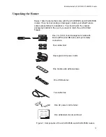
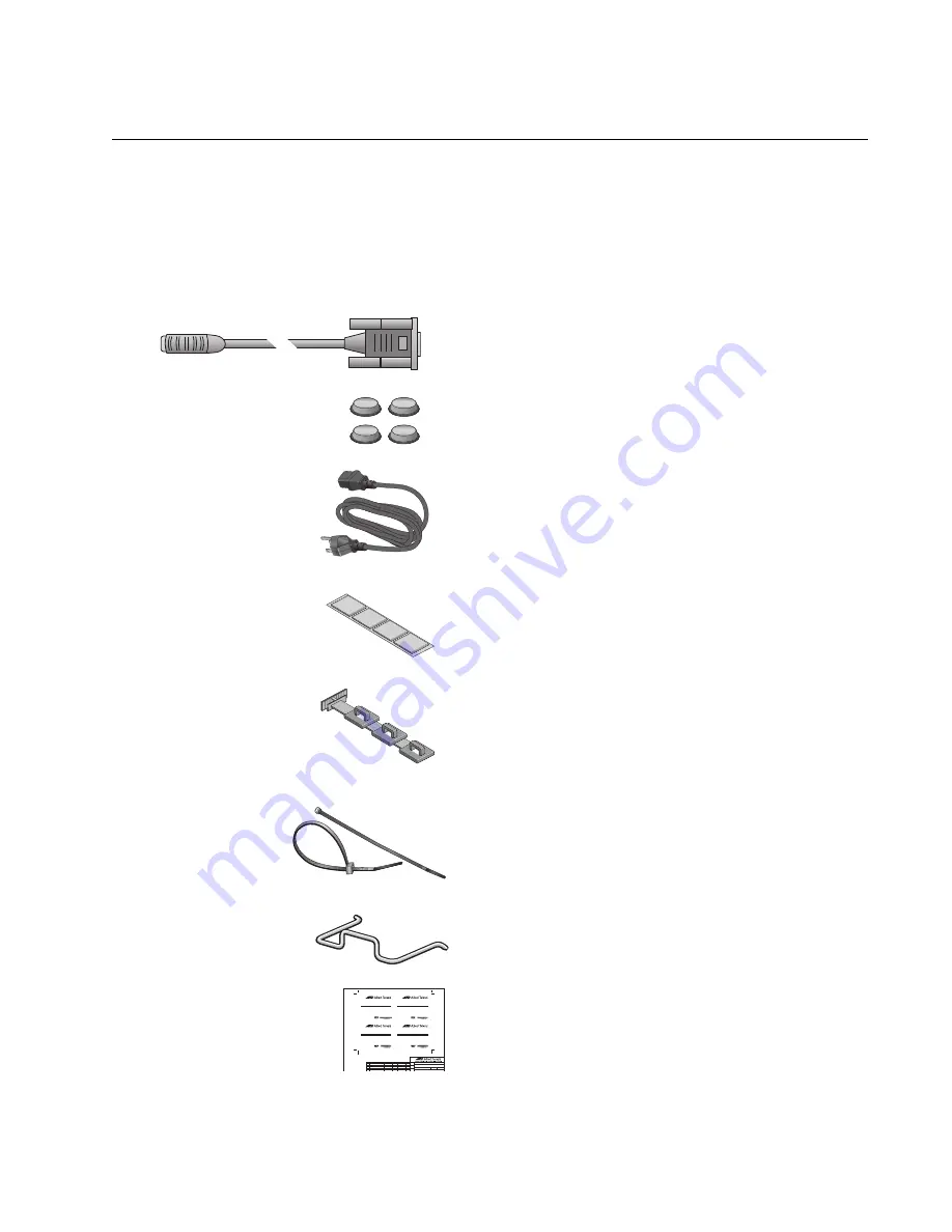
Figure 1 lists the items that come with the AT-AR3050S and AT-AR4050S
routers. If any item is missing or damaged, contact your Allied Telesis
sales representative for assistance. You should retain the original
packaging material in the event you need to return the unit to Allied
Telesis.
Figure 1. Components of the AT-AR3050S and AT-AR4050S routers
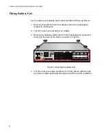
Four rubber feet
One 2 m (6.6 ft) local management cable with
RJ-45 (8P8C) and DB-9 (D-sub 9-pin female)
connectors.
One double-side adhesive tape
One regional AC power cords
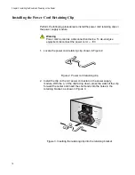
One USB retainer
Two cable ties
One AC power cord retainer
One addendum document sheet
REV Description
Drawn/Date Initials Checked/Date Initials
A
ECO C025999
Oct 2014
AD
Oct 2014
WG
AT NGFW Device insert
613-002048
613-002048_RevA
A
1 OF 1
PRODUCT
TITLE
DWG No
FILE NAME
SCALE
SHEET
SIZE
REV
UNITS
AT NGFW Device insert
1:1
A4
mm
See Installation Guide before connecting the power source.
Product Documentation
Allied Telesis is committed to providing the highest quality products while
minimizing the impact on the environment. As part of our green eco-friendly approach, you
now have access to the latest product documentation at
www.alliedtelesis.com/support.
For a device
WITH
Local Management Console Port: Connect a terminal
emulator using the management cable provided at either 9600 Baud or 115,200
Baud depending on your product - see your product Installation Guide.
For a device
WITHOUT
Local Management Console Port: Connect to one
of Ethernet ports and log on with a web browser at http://192.168.1.1/.
LOGIN: In either case, the default User Name is “manager” and default Password
is “friend”.
Summary of Contents for AT-AR3050S
Page 8: ...Figures 8 ...
Page 10: ...Tables 10 ...
Page 14: ...Preface 12 ...
Page 50: ...Chapter 2 Beginning the Installation 16 ...
Page 76: ...Chapter 5 Troubleshooting 40 ...


