Installation Guide for AT-AR3050S, AT-AR4050S Routers
15
Front and Back Panels
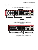
The front panel of the AT-AR3050S router is shown in Figure 1.
Figure 1. Front panel of the AT-AR3050S router
The front panel of the AT-AR4050S router is shown in Figure 2.
Figure 2. Front panel of the AT-AR4050S router
CLASS 1
LASER PRODUCT
CONSOLE
SD
SD
FAULT
PWR
FNC1
FNC2
RESET
1
2
3
4
5
6
7
8
1
2
BYPASS
1
2
1
2
USB
HA
FDX
HDX
COL
READY
FAULT
READY
FAULT
MASTER
STANDBY
ETH
ETH
AR3050S
1000 LINK
ACT
100 LINK
ACT
AR3050S
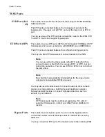
10/100/1000 Base-T Ports
Intake Air Vents
Management Panel
SFP Slots
ETH Ports
Bypass Ports
CLASS 1
LASER PRODUCT
CONSOLE
SD
SD
FAULT
PWR
FNC1
FNC2
RESET
1
2
3
4
5
6
7
8
1
2
BYPASS
1
2
1
2
USB
HA
FDX
HDX
COL
READY
FAULT
READY
FAULT
MASTER
STANDBY
ETH
ETH
1000 LINK
ACT
100 LINK
ACT
AR4050S
10/100/1000 Base-T Ports
Intake Air Vents
Management Panel
SFP Slots
ETH Ports
Bypass Ports
Summary of Contents for AT-AR3050S
Page 8: ...Figures 8 ...
Page 10: ...Tables 10 ...
Page 14: ...Preface 12 ...
Page 50: ...Chapter 2 Beginning the Installation 16 ...
Page 76: ...Chapter 5 Troubleshooting 40 ...


