


506892-01
Page 12 of 64
Issue 1251
NOTE:
Do not operate the furnace in the heating mode
with an external static pressure that exceeds 0.8 inches w.c.
Higher external static pressures may cause erratic limit
operation.
Ensure that you have made a seal between the supply air
plenum and the furnace and between the furnace and the
return air plenum.
Supply Air Plenum
If the furnace is installed without a cooling coil, a removable
access panel should be installed in the supply air duct. The
access panel should be large enough to permint inspection
(either by smoke or reflected light) of the heat exchanger
for leaks after the furnace is installed.
Return Air Plenum
Return air must not be drawn from a room where this furnace,
or any other gas fueled appliance (i.e., water heater), or
carbon monoxide producing device (i.e., wood fireplace) is
installed. When return air is drawn from a room, a negative
pressure is created in the room. If a gas appliance is
operating in a room with negative pressure, the flue products
can be pulled back down the vent pipe and into the room.
This reverse flow of the flue gas may result in incomplete
combustion and the formation of carbon monoxide gas. This
toxic gas might then be distributed throughout the house by
the furnace duct system.
Venting
A 4 inch diameter flue transition is factory installed on all
models. Modifying or removing the flue transition will cause
the unit to operate unsafely and will void the unit certification.
The vent connector does not require insulation.
This series of units are classified as fan assisted Category I
furnaces when vertically vented according to the latest edition
of National Fuel Gas Code (NFPA 54
1
ANSI Z223.1). A fan
assisted Category I furnace is an appliance equipped with
an integral mechanical means to either draw or force
combustion products through the combustion chamber
and/
or
heat exchanger.
This unit is not approved for use
with horizontal venting.
NOTE:
Use these instructions as a guide. They do not
supersede local codes. This furnace must be vented
according to all local codes, these installation instructions,
and the provided venting tables in these instructions.
The venting tables in this manual were extracted from the
National Fuel Gas Code (NFPA
541
ANSI Z223.1) and are
provided as a guide for proper vent installation. Proper
application, termination, construction and location of vents
must conform to local codes having jurisdiction. In the
absence of local codes, the NFGC serves as the defining
document.
Refer to the tables and the venting information contained in
these instructions to properly size and install the venting
system.
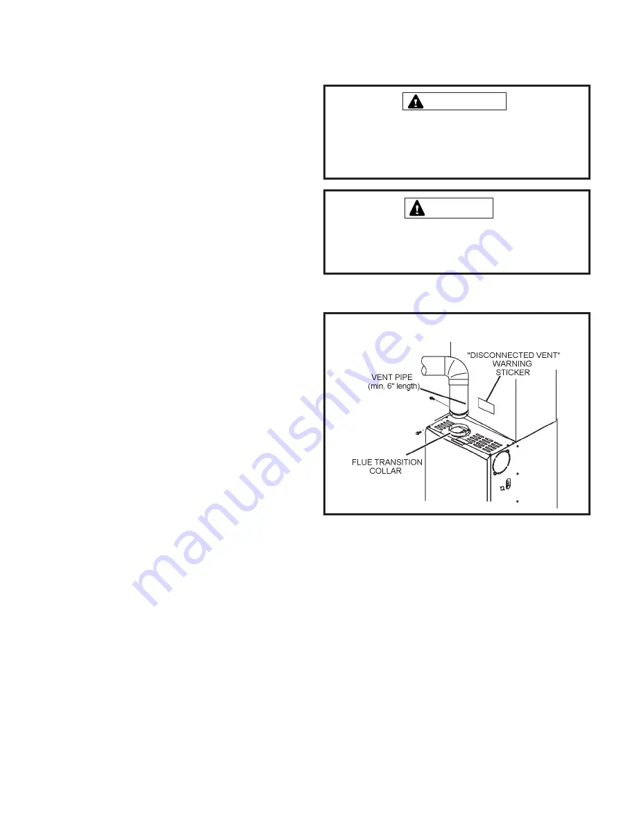
Use self drilling sheet metal screws or a mechanical fastener
to firmly secure the vent pipe to the round collar of the flue
transition. If self drilling screws are used to attach the vent
pipe, it is recommended that three be used. Drive one self
drilling screw through the front and one through each side
of the vent pipe and collar. See Figure 15.
Install the first vent connector elbow at a minimum of six
inches (152 mm) from the furnace vent outlet.
VENT CONNECTION
Figure 15
WARNING
Asphyxiation hazard. The exhaust vent for this furnace
must be securely connected to the furnace flue transition
at all times.
Once the venting system is installed, attach the
“Disconnected Vent” warning sticker to a visible area of
the plenum near the vent pipe. The warning sticker is
provided in the bag assembly.
IMPORTANT
Summary of Contents for A80DS2V
Page 3: ...506892 01 Page 3 of 64 Issue 1251 EXPANDED VIEW Figure 1...
Page 24: ...506892 01 Page 24 of 64 Issue 1251 Figure 22...
Page 30: ...506892 01 Page 30 of 64 Issue 1251 Figure 24 A80DS2V Schematic Wiring Diagram...
Page 31: ...506892 01 Page 31 of 64 Issue 1251 Typical A80DS2V Field Wiring Diagram Figure 25...
Page 32: ...506892 01 Page 32 of 64 Issue 1251 Integrated Control Figure 26...
Page 50: ...506892 01 Page 50 of 64 Issue 1251 Integrated Control Diagnostic Codes...
Page 51: ...506892 01 Page 51 of 64 Issue 1251 Integrated Control Diagnostic Codes continued...
Page 52: ...506892 01 Page 52 of 64 Issue 1251 Integrated Control Diagnostic Codes continued...
Page 53: ...506892 01 Page 53 of 64 Issue 1251 Integrated Control Diagnostic Codes continued...
Page 54: ...506892 01 Page 54 of 64 Issue 1251 Integrated Control Diagnostic Codes continued...
Page 55: ...506892 01 Page 55 of 64 Issue 1251 Program Unit Capacity Size Mode...
Page 56: ...506892 01 Page 56 of 64 Issue 1251 Troubleshooting Heating Sequence of Operation...
Page 57: ...506892 01 Page 57 of 64 Issue 1251 Troubleshooting Heat Sequence of Operation continued...
Page 58: ...506892 01 Page 58 of 64 Issue 1251 Troubleshooting Heat Sequence of Operation continued...
Page 59: ...506892 01 Page 59 of 64 Issue 1251 Troubleshooting Heat Sequence of Operation continued...
Page 60: ...506892 01 Page 60 of 64 Issue 1251 Troubleshooting Continuous Fan Sequence of Operation...
Page 61: ...506892 01 Page 61 of 64 Issue 1251 Start Up Performance Check List UNIT SET UP...
Page 62: ...506892 01 Page 62 of 64 Issue 1251 Start Up Performance Check List continued...


