background image

© Copyright, Alliance Laundry Systems LLC – DO NOT COPY or TRANSMIT

Installation/Operation Supplement

11

F232145 (EN)

For 18, 20, 25, 27, 30 and 35 Pound 
Capacity Machines

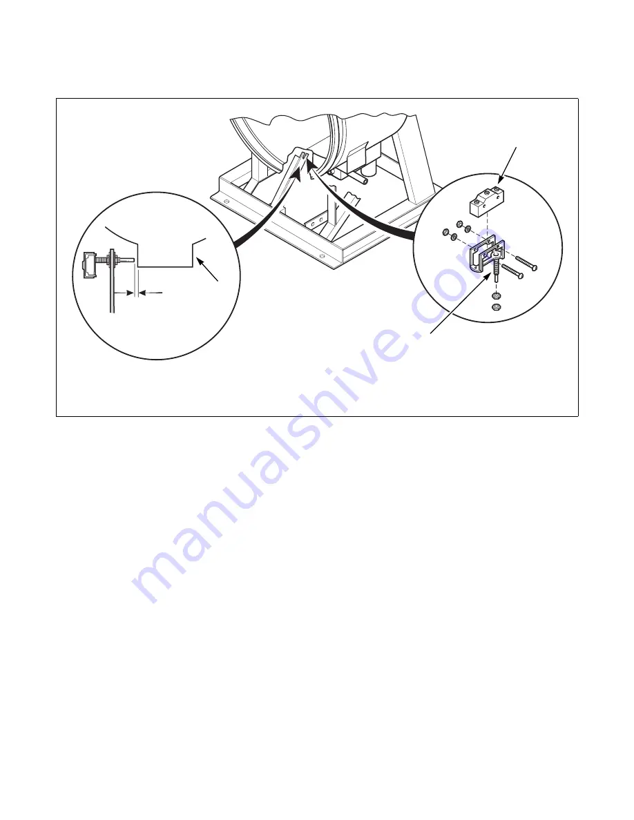
Figure 1 

CHM1995N

1

Sump

3

Vibration Switch

2

Gap Distance

4

Switch Extension

CHM1995N

1

2

3

4
Summary of Contents for CHM166C

Page 1: ...mount Operating Instructions Part No F232145R6EN November 2005 This manual is only a Supplement Refer to Installation Manualand Operation Maintenance Manual for full instructions Keep These Instructions for Future Reference If this machine changes ownership this manual must accompany machine ...

Page 2: ......

Page 3: ...ent Table of Contents Safety Information 3 Important Safety Instructions 3 Specifications and Dimensions 5 Gap Setting for Vibration Switch Variable Speed and Fixed Speed Models 8 Dimensional Clearances 16 Dimensions 17 18 20 25 27 30 35 40 50 60 and 80 Models 17 125 Model 19 Electrical Specifications 20 Operation 25 Instructions for EDC Control 27 Instructions for Mechanical Timer 29 Instructions...

Page 4: ... Copyright Alliance Laundry Systems LLC DO NOT COPY or TRANSMIT 2 F232145 EN Installation Operation Supplement Notes ...

Page 5: ... substances to the wash water These substances give off vapors that could ignite or explode 5 Under certain conditions hydrogen gas may be produced in a hot water system that has not been used for two weeks or more HYDROGEN GAS IS EXPLOSIVE If the hot water system has not been used for such a period before using a washing machine or combination washer dryer turn on all hot water faucets and let th...

Page 6: ... softener or product 18 Keep washer in good condition Bumping or dropping the washer can damage safety features If this occurs have washer checked by a qualified service person 19 Replace worn power cords and or loose plugs 20 Be sure water connections have a shut off valve and that fill hose connections are tight CLOSE the shut off valves at the end of each wash day 21 Loading door MUST BE CLOSED...

Page 7: ... 706 321 820 373 Domestic shipping weight lbs kg 428 194 470 214 545 245 680 309 744 338 875 398 Domestic shipping volume ft3 m3 28 0 8 33 0 9 35 1 0 39 1 09 42 6 1 19 53 1 5 Export shipping weight lbs kg 480 218 530 241 588 267 760 345 846 385 1020 464 Export shipping volume ft3 m3 30 1 0 86 36 7 1 03 39 6 1 11 47 1 1 32 54 1 1 51 58 7 1 67 Wash Cylinder Information Cylinder diameter in mm 21 533...

Page 8: ...ion Average power used per cycle kW hr 0 20 0 25 0 25 0 30 0 34 0 42 Average HVAC load Btu hr 425 400 400 510 510 700 Drive Train Information Number of motors in drive train 1 1 1 1 1 1 Wash reverse power HP kW 0 18 0 13 0 25 0 19 0 25 0 19 0 40 0 30 0 40 0 30 0 55 0 41 High extract power HP kW 1 0 0 746 1 4 1 04 1 4 1 04 1 8 1 3 1 8 1 3 2 7 2 01 Cylinder Speeds Wash reverse speed RPM 53 55 47 47 ...

Page 9: ... 2 13 1 2 13 1 2 13 Number of steam inlets 1 1 1 1 1 1 1 Steam required to raise bath water temperature 10 F 6 C LOW 1 05 0 75 1 4 1 01 1 44 1 03 2 06 1 48 2 09 1 51 2 76 1 99 2 76 1 99 HIGH 1 4 1 01 1 59 1 15 1 91 1 37 2 69 1 94 2 84 2 04 3 59 2 59 3 59 2 59 Average steam use per cycle bhp kg 0 71 11 1 0 87 13 6 0 97 15 2 1 4 21 6 1 43 22 4 1 84 28 9 1 84 28 9 Electrical Heating Optional Total el...

Page 10: ... 3 4 and 5 2 Measure the gap distance when the switch is in both the open and closed positions The specifications should be at the minimum switch gap setting when the switch is open and at the maximum switch gap setting when the switch is closed If these distances are not correct adjust the balance switch to these specifications NOTE The standard position of the switch is open or non tripped 3 Tig...

Page 11: ...g weight lbs kg 476 215 588 267 731 332 846 385 967 439 1020 463 1506 678 2701 1225 Export shipping volume ft3 m3 30 1 0 86 39 6 1 11 47 1 1 32 54 1 1 51 58 7 1 67 58 7 1 67 109 5 3 1 173 4 8 Wash Cylinder Information Cylinder diameter in mm 21 533 24 610 26 1 4 667 26 1 4 667 30 762 30 762 36 914 42 1060 Cylinder depth in mm 13 3 4 349 16 406 18 3 8 467 20 1 4 514 20 508 22 559 22 559 24 609 Cyli...

Page 12: ...al force Gs 40 40 40 40 40 40 40 40 Medium extract centrifugal force Gs 85 85 85 85 85 85 85 85 High extract centrifugal force Gs 140 140 140 140 140 140 140 140 Balance Detection Vibration switch installed Standard Standard Standard Standard Standard Standard Standard Standard Direct Steam Heating Optional Steam inlet connection size in mm 1 2 13 1 2 13 1 2 13 1 2 13 1 2 13 1 2 13 1 2 13 3 4 19 N...

Page 13: ... Systems LLC DO NOT COPY or TRANSMIT Installation Operation Supplement 11 F232145 EN For 18 20 25 27 30 and 35 Pound Capacity Machines Figure 1 CHM1995N 1 Sump 3 Vibration Switch 2 Gap Distance 4 Switch Extension CHM1995N 1 2 3 4 ...

Page 14: ...s LLC DO NOT COPY or TRANSMIT Installation Operation Supplement F232145 EN 12 For 40 and 50 Pound Capacity Variable Speed and Fixed Speed Machines Figure 2 CHM2000N 1 Sump 3 Vibration Switch 2 Gap Distance 4 Switch Extension 1 2 3 4 3 4 ...

Page 15: ...or TRANSMIT Installation Operation Supplement 13 F232145 EN For 60 Pound Capacity Variable Speed and Fixed Speed Machines Figure 3 CHM1999N 1 Lower Bracket 4 Balance Bolt 2 Upper Bracket 5 Lock Nut 3 Vibration Switch 6 Gap Distance CHM1999N 6 2 2 4 3 5 1 ...

Page 16: ...liance Laundry Systems LLC DO NOT COPY or TRANSMIT Installation Operation Supplement F232145 EN 14 For 80 Pound Capacity Machines Figure 4 CHM1998N 1 Switch Extension 3 Vibration Switch 2 Gap Distance CAB1998N 1 2 3 ...

Page 17: ...t Alliance Laundry Systems LLC DO NOT COPY or TRANSMIT Installation Operation Supplement 15 F232145 EN For 125 Pound Capacity Machines Figure 5 CHM1993N 1 Vibration Switch 3 Switch Extension 2 Gap Distance 1 2 3 ...

Page 18: ...mm 34 1 16 in 865 mm 41 1 2 in 1054 mm 48 in 1219 mm C 1 in 25 mm 1 in 25 mm 1 in 25 mm 1 in 25 mm 1 in 25 mm 1 in 25 mm 1 in 25 mm 1 in 25 mm 12 in 300 mm D 16 3 8 in 416 mm 16 3 8 in 416 mm 19 1 4 in 490 mm 19 1 4 in 490 mm 22 in 560 mm 22 in 560 mm 22 in 560 mm 25 in 635 mm 26 1 4 in 667 mm E 25 5 8 in 650 mm 29 7 16 in 705 mm 30 1 2 in 775 mm 34 in 864 mm 36 in 914 mm 37 1 2 in 953 mm 38 3 4 i...

Page 19: ...0 35 40 50 60 and 80 Models CHM2019N 1 Supply Dispenser 5 Hot Water Inlet 2 Input Power Block 6 Extra Inlet Valve 3 External Chemical Supply Signal Terminal Strip OPL only 7 External Chemical Supply Inlet OPL only 8 Vacuum Breaker 4 Cold Water Inlet 9 Drain Outlet Figure 7 CHM2019N 1 2 3 4 6 5 7 8 9 A B C D F E G H L M K N O P J I R Q S ...

Page 20: ...2 1 2 in 318 mm 15 1 4 in 387 mm 14 1 4 in 362 mm 15 7 16 in 392 mm 20 3 4 in 527 mm 20 3 4 in 527 mm 22 1 4 in 572 mm J 11 1 2 in 292 mm 11 1 2 in 292 mm 14 3 4 in 375 mm 10 13 16 in 275 mm 14 7 16 in 367 mm 19 3 4 in 502 mm 19 3 4 in 502 mm 14 7 16 in 378 mm K 3 1 2 in 89 mm 3 1 2 in 89 mm 3 3 4 in 95 mm 2 3 4 in 70 mm 3 13 16 in 97 mm 3 1 2 in 89 mm 3 1 2 in 89 mm 3 7 16 in 87 mm L 34 1 2 in 87...

Page 21: ...Outlet 4 Hot Water Inlet Figure 8 I B023I H P 5 7 3 1 2 6 J A B C D E F G Q 4 R S T K L N O M Machine Capacity Dimensions A 1016 mm 40 in K 1041 mm 41 in B 768 mm 30 12 in L 978 mm 38 5 in C 737 mm 29 in M 851 mm 33 5 in D 203 mm 8 in N 756 mm 29 75 in E 1219 mm 48 in O 610 mm 24 in F 1283 mm 50 5 in P 330 mm 13 in G 1422 mm 56 75 in Q 124 mm 4 88 in H 25 mm 1 in R 1622 mm 63 88 in I 1791 mm 70 5 ...

Page 22: ... 60 1 2 10 20 12 4 42 45 6 16 Variable Speed Models Q 200 240 50 60 3 3 8 3 8 15 14 2 5 N A N A N A N A NOTE Wire sizes shown are for copper THHN 90 conductor per NEC article 310 Table 7 Electrical Specifications 25 27 and 30 Pound Capacity Models Voltage Designation Standard Electric Heat Code Voltage Cycle Phase Wire Full Load Amps Circuit Breaker AWG mm 2 Full Load Amps Circuit Breaker AWG mm 2...

Page 23: ... 5 N A X 200 240 50 60 1 or 3 2 or 3 5 9 5 9 15 14 2x2 5 3x2 5 N A NOTE Wire sizes shown are for copper THHN 90 conductor per NEC article 310 Table 9 Electrical Specifications 40 Pound Capacity Models Voltage Designation Standard Electric Heat Code Voltage Cycle Phase Wire Full Load Amps Circuit Breaker AWG mm 2 Full Load Amps Circuit Breaker AWG mm 2 2 Speed Models C 380 415 50 3 4 5 15 14 2 5 26...

Page 24: ...240 50 3 3 12 20 12 4 64 70 4 25 E 220 240 50 1 2 15 30 10 6 37 40 8 10 F 440 480 60 3 3 6 15 14 2 5 39 50 6 16 J 200 50 3 3 10 20 12 3 x 4 N A O 208 240 60 3 3 10 20 12 4 64 70 4 25 Y 208 240 60 1 2 15 30 10 6 37 40 8 10 Variable Speed Models N 440 480 50 60 3 3 4 15 14 2 5 41 6 45 8 10 P 380 415 50 60 3 3 4 15 14 2 5 36 5 40 8 10 Q 200 240 50 60 3 3 6 3 15 14 2 5 62 6 70 4 25 T 200 240 50 60 1 2...

Page 25: ... 37 50 8 10 0 D 220 240 50 3 3 7 20 12 4 0 64 70 4 25 0 F 440 480 60 3 3 4 15 14 2 5 41 50 8 10 0 H 380 60 3 3 3 20 12 4 0 33 50 8 10 0 J 200 50 3 3 8 20 12 4 0 55 60 6 16 0 O 208 240 60 3 3 7 20 12 4 0 64 70 4 25 0 X 200 240 50 60 1 3 2 3 9 20 12 4 0 N A N A N A N A Variable Speed Models N 440 480 50 60 3 3 4 15 14 2 5 42 50 8 10 0 P 380 415 50 60 3 3 5 15 14 2 5 37 40 8 10 0 Q 200 240 50 60 3 3 ...

Page 26: ...415 50 60 3 3 4 5 15 14 2 5 37 40 8 10 Q 200 240 50 60 3 3 12 4 20 12 4 87 4 90 2 35 NOTE Wire sizes shown are for copper THHN 90 conductor per NEC article 310 Table 13 Electrical Specifications 125 Pound Capacity Models Voltage Designation Standard Electric Heat Code Voltage Cycle Phase Wire Full Load Amps Circuit Breaker AWG mm 2 Full Load Amps Circuit Breaker AWG mm 2 Variable Speed Models N 44...

Page 27: ...ntinued CHM493N CHM493N CHM494N CHM494N CHM495N CHM495N CHM496N CHM496N CHM497N CHM497N CHM498N CHM498N CHM499N CHM499N CHM500N CHM500N CHM501N CHM501N CHM502N CHM502N CHM503N CHM503N Table 15 Continued Symbol Description Edit Down Start Select Mode Wash Add Bleach Rinse Spin Door Open Clean Filter Reduced Spin keypad Extra Wash keypad Table 15 Continued CHM504N CHM504N CHM505N CHM505N CHM506N CHM...

Page 28: ...arm Permanent Press Warm Normal Wash Cold Permanent Press Exit Cold Hand Wash Edit Up Gentle Wash Edit Down Cold Time Start Enter Wash Temperature Display Vend Price Actuation CHM1980N 95C CHM1980N CHM1981N 95C CHM1981N CHM1982N 60C CHM1982N CHM1983N 60C CHM1983N CHM1984N 40C CHM1984N CHM1985N 40C CHM1985N CHM1986N CHM1986N CHM1987N 30C CHM1987N CHM1988N CHM1988N CHM1989N CHM1989N CHM1990N CHM1990...

Page 29: ...oad to capacity whenever possible DO NOT OVERLOAD Refer to Figure 10 Figure 10 4 Close door and turn handle counterclockwise until button pops out Refer to Figure 11 Figure 11 5 Select cycle and temperature Refer to Figure 12 6 For machines equipped with a coin meter Insert coins Refer to Figure 12 Figure 12 U001IE1B U003IE1A U001IE1B U005IE1B B148R U005IE1B HOT WARM PERM PRESS NORMAL INSERT COIN ...

Page 30: ...s SPEC then CYCL extra options such as high speed extract or extra rinse are available If desired insert coins card to meet additional price shown on display If not desired wait 30 seconds for earlier cycle selection to continue 10 Add bleach to container 2 when ADD BLEACH light is lit Refer to Figure 15 Figure 15 11 Cycle is complete when display reads 00 B149R B155R 1 Detergent 2 Bleach 3 Soften...

Page 31: ...sh button and turn handle clockwise to open Refer to Figure 16 Figure 16 For non coin models Press and hold the DOOR UNLOCK button on the left side of the control panel while performing the above step Refer to Figure 17 Figure 17 3 Load to capacity whenever possible DO NOT OVERLOAD Refer to Figure 18 Figure 18 4 Close door and turn handle counterclockwise until button pops out Refer to Figure 19 F...

Page 32: ...ser Refer to Installation and Programming Manuals 7 For coin models Insert required number of coins to start machine Refer to Figure 21 Figure 21 For non coin models Press the Start button Refer to Figure 22 Figure 22 8 Add bleach to container 2 when ADD BLEACH light is lit Refer to Figure 23 Figure 23 U002IE1A B157R 1 Detergent 2 Bleach 3 Softener SPIN CYCLE INDICATOR WASH CYCLES PREWAS H W A S H...

Page 33: ...2 Push button and turn handle clockwise to open Refer to Figure 24 Figure 24 For non coin models Press and hold the DOOR UNLOCK button on the left side of the control panel while performing the above step Refer to Figure 25 Figure 25 3 Load to capacity whenever possible DO NOT OVERLOAD Refer to Figure 26 Figure 26 4 Close door and turn handle counterclockwise until button pops out Refer to Figure ...

Page 34: ...efer to Figure 29 7 For coin models Insert required number of coins to start machine Refer to Figure 28 Figure 28 8 For non coin models Press the Start key Refer to Figure 29 Figure 29 9 When applicable add beach to container 2 when the display reads bLCH Refer to Figure 30 Figure 30 NOTE To stop a cycle at any time press the Stop key Non coin models only NOTE To display the temperature of the wat...

Page 35: ...fer to Figure 31 Figure 31 3 Load to capacity whenever possible DO NOT OVERLOAD Refer to Figure 32 Figure 32 4 Close door and turn handle counterclockwise until button pops out Refer to Figure 33 Figure 33 5 The default wash cycle will display Refer to Figure 34 NOTE Perm Press Cold is the default cycle for coin models if none is selected Perm Press Hot is the default cycle for OPL models U001I U0...

Page 36: ...9 If the machine is a card operated unit insert and remove card Contact the card reader manufacturer for details 10 If the unit is interfaced to a central remote pay system go to the central remote pay console make payment and select the machine Contact the pay system manufacturer for more details 11 When applicable add bleach to compartment 2 when the ADD BLEACH LED is lit 12 Press the desired wa...

Page 37: ...oin box and press START keypad 1 Turn on main power source circuit breaker 2 Push button and turn handle clockwise to open Refer to Figure 36 Figure 36 3 Load to capacity whenever possible DO NOT OVERLOAD Refer to Figure 37 Figure 37 4 Close door and turn handle counterclockwise until button pops out Refer to Figure 38 Figure 38 5 The default wash cycle will display Refer to Figure 39 NOTE The def...

Page 38: ...tral remote pay console make payment select the machine and follow central remote pay system instructions 11 Press the desired wash cycle key if it hasn t already been selected NOTE Once START keypad is pressed the selected wash cycle is locked in and wash cycle will begin 12 Press the START keypad 13 Add bleach if and when prompted display will show bLCH signal will sound on and off for 45 second...

Reviews: