background image


43 


C34 


PARTS SECTION 


Summary of Contents for C 34

Page 1: ...Y OPERATORS PARTS MANUAL English version Turfmech Machinery Limited Hangar 5 New Road Hixon Stafford ST18 0PJ United Kingdom Tel 44 0 1889 271503 Fax 44 0 1889 271321 Sales allett co uk www allett co uk ...

Page 2: ...2 ...

Page 3: ...3 ATTENTION THIS SYMBOL MEANS BE ALERT YOUR SAFETY IS INVOLVED READ THIS MANUAL BEFORE USING AN ALLETT C34 CYLINDER MOWER IT IS ESSENTIAL THAT OPERATORS STUDY IT FOR THEIR OWN SAFETY ...

Page 4: ...e 17 Loading a driven cartridge 18 Loading a non driven cartridge 18 Removing a cartridge 18 Operation cartridges 19 SAFETY NOTICE 19 Cleaning the mower 20 Adjusting the bottom blade 20 Adjusting the height of cut 23 Cylinder and bottom blade grinding reconditioning 25 Operation other cartridges 25 Maintenance schedule 26 Maintenance 28 SAFETY NOTICE 28 Daily checks maintenance 30 Checking engine ...

Page 5: ...om storage 38 Specification Base machine 40 Specification Cartridges 41 Cutting rates 41 MODEL C34 Front Roller Assembly BOM FIG 1 43 MODEL C34 Countershaft Assembly Engine Side BOM FIG 2A 47 MODEL C34 Countershaft Assembly Brake Side BOM FIG 2B 50 MODEL C34 Kickstand Assembly BOM FIG 3 52 MODEL C34 Handle Bar Assembly BOM FIG 4 54 MODEL C34 Lower Handle Bar Assembly BOM FIG 5 56 MODEL C34 Rear Ro...

Page 6: ...serviced and repaired only by persons who are familiar with its particular characteristics and who are acquainted with the relevant safety procedures The safety precautions outlined in this manual and all other generally recognised regulations on safety must be observed at all times Any arbitrary modifications carried out to a C34 mower may relieve Turfmech Machinery Limited of liability for any r...

Page 7: ...e exposed to a daily personal noise exposure level in excess of 98 dB A LEP d Sound power level The maximum sound power level is 98 dB A measured in accordance with EC Directive 2000 14 EC Ear protectors with good attenuation in the 63 8000 Hz frequency range should be used Employers of personnel using the C34 mower are advised to read and understand the HSE publication Noise at Work Guidance for ...

Page 8: ... of Directive 98 37 EC Essential Health and Safety Requirements Relating to the Design and Construction of Machinery and Safety Components Also Directive 89 336 EEC amended by 92 31 EEC Electromagnetic Compatibility Also Directive 2000 14 EC Noise emission in the environment by equipment for use outdoors Standards used BS EN 836 1997 BS EN ISO 12100 2003 parts 1 and 2 Authorised signature J C Arch...

Page 9: ...cially children or animals are nearby Bear in mind that the operator is responsible for accidents or hazards occurring to other people or their property Do not attempt to ride on the mower or carry passengers All operators should seek and obtain professional and practical instruction Such instruction should emphasise The need for care and concentration while working with the C34 mower The need to ...

Page 10: ...ecessary Petrol is highly flammable therefore Store fuel in containers specially designed for this purpose Refuel outdoors only and do not smoke while refuelling Add fuel before starting the engine Never remove the cap from the fuel tank or add petrol while the engine is running or while the engine is hot Allow the engine to cool for at least two minutes before refuelling Be aware that the engine ...

Page 11: ...ngine at excessive speed will lead to increased wear and tear and increases the risk of injury Before leaving the operator position Disengage drive to the rollers Disengage drive to the cylinder Engage the parking brake Switch the on off switch on the handlebars to the OFF position Engage the parking brake disengage drive to the cutting cylinder switch off the engine and ensure the cylinder is com...

Page 12: ...ent entrapment of the fingers between moving blades and fixed parts during maintenance activities Allow the engine and exhaust to cool before storing in any enclosure If the fuel tank has to be drained this should be done outdoors Always chock the roller when the mower is being left in storage Health and Safety at Work Act In accordance with section 6 of the Health and Safety at Work Act 1974 the ...

Page 13: ...13 Decal positions Description Large Allett logo Location Grass box Quantity 1 Description Small Allett logo Location Handle bars Quantity 1 ...

Page 14: ...hly inspected and all objects which are likely to cause damage to the machine or endanger the operator or bystanders are removed WARNING PREVENT ACCIDENTS Operate safely on slopes By following safe working practices By understanding and following the relevant safety precautions outlined in this manual Refer Safety Precautions WARNING PREVENT ACCIDENTS Never attempt to start the mower indoors Alway...

Page 15: ...eck engine oil level refer to the Honda engine manual for the recommended oil specification Check fuel level clean around the fuel filler cap before removing it Do not overfill the tank The fuel filler cap must be firmly secured in order to prevent fuel leakage during operation Always use clean fresh unleaded petrol Purchase fuel in quantities which can be used within 30 days Never mix oil with pe...

Page 16: ...e to the ON position After the engine has started wait a few seconds then return the choke to the off position Allow the engine to warm up before starting to use the mower Stopping the engine To stop the engine turn the on off switch on the handlebars to OFF The engine can also be stopped by turning the engine mounted on off switch to the OFF position If either of these measures do not stop the en...

Page 17: ...ever to the desired position Transporting the machine Ensure that the trailer meets all Road Traffic Act requirements Secure the mower on the trailer positioning it adjacent to the trailer headboard Ensure that the mower parking brake is engaged Ensure that the fuel shut off tap is set to the OFF position WARNING on long journeys check the mower regularly so as to ensure that it is still securely ...

Page 18: ... the studs on the drive plate When lined up push the cartridge all the way to the right when facing the mower Finally rotate the locking knob clockwise to secure the cartridge Loading a non driven cartridge Before loading the cartridge ensure that the locking knob on the side of the mower chassis is loosened off by rotating it anti clockwise Carefully lift the cartridge using the two red handles a...

Page 19: ...ake and wait until the cylinder has completely stopped rotating WARNING PREVENT ACCIDENTS Check that all of the belt guards are attached and are in a satisfactory condition If any are missing replace before starting the mower WARNING PREVENT ACCIDENTS Do not engage the drive to the cutting cylinder unless the mower is moving forward on a grass surface WARNING PREVENT ACCIDENTS Always wear gloves w...

Page 20: ...covered by the Turfmech Machinery Limited warranty Adjusting the bottom blade WARNING PREVENT ACCIDENTS Always wear gloves when handling the cylinder Tilt the mower backwards Hold a thin piece of paper between the edge of the bottom blade and the cutting cylinder Turn the cutting cylinder slowly If the blade is set properly the paper should cut cleanly along its full length If it does not then pro...

Page 21: ...r clockwise to increase the gap Rotate the adjuster anti clockwise to decrease the gap Clockwise Anti clockwise Adjust the clearance between the bottom blade and the cutting cylinder so that the paper is cleanly cut at all points across the blade Frequently use the paper test between each adjustment ...

Page 22: ...arting the engine after having tilted the mower allow it to sit level for a short time to allow the engine oil to settle WARNING PREVENT DAMAGE The adjusters can sometimes become very tight and may be hard to turn if this is the case Slacken off the grub screw on the collar behind the adjuster as shown rotate the adjuster anti clockwise 1 8th of a turn Tighten the grub screw Check the adjuster it ...

Page 23: ...and the desired groomer height Y as shown below Once adjusted position the setting bar so that the underside of the bolt head X rests on top of the leading edge of the bottom blade and the rearward end of the bar makes contact with the rear roller as shown Adjust the height of the front roller until the setting bar just touches it If a groomer is fitted adjust the height of the groomer until the e...

Page 24: ...t To alter the position of the groomer Firstly ensure that the groomer is lowered and isn t in the transport position To do this you must loosen the two knobs on each side of the cartridge If the groomer drops it was in the travel position Place the groomer in its lowest position tighten the knobs and check the height again To adjust the height of the groomer turn the two adjusters the same amount...

Page 25: ...ttom blade Poorly maintained parts will lead to a poor quality of cut It is advised that the grinding reconditioning of the cylinder and bottom blade be carried out by either Turfmech Machinery Limited or a registered Allett dealer Operation other cartridges For relevant information on how to set up and maintain cartridges refer to specific cartridge manuals ...

Page 26: ... level Guards in place Tyre pressures if fitted Cutting cylinder Fasteners Chain and belt tension Spark plugs Clean Debris grass from mower Engine cooling baffles Fuel sediment bowl Air filter elements Inside guards Test Parking brake On off switches Drive engagement Replace Engine oil Spark plugs Air filter elements Fuel hose ...

Page 27: ...27 ...

Page 28: ...ing out maintenance procedures it is essential that The engine is not running The parking brake is engaged The cutter head clutch is disengaged The rear roller drive is disengaged The safety precautions in this manual have been read and understood WARNING PREVENT ACCIDENTS Engine oil will be hot after machine use Allow the engine to cool before working on the machine particularly when changing oil...

Page 29: ...RTANT PREVENT ENVIRONMENTAL DAMAGE When disposing of hazardous waste products take them to an authorised disposal site Waste products must not be allowed to contaminate surface water drains or sewerage systems ...

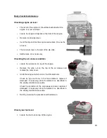
Page 30: ...eaner condition Locate the air cleaner on top of the engine Remove the wing nut on the top of the air cleaner and remove the outer cover Undo the wing nut which retains the filter elements Check for rips and tears in the foam element replace if damaged If necessary clean the element as described in the weekly maintenance section Check the condition of the main paper element replace if damaged If n...

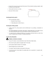
Page 31: ...he condition of both the cylinder and bottom blade Poorly maintained parts will lead to a poor quality of cut It is advised that the grinding reconditioning of the cylinder and bottom blade be carried out by either Turfmech Machinery Limited or a registered Allett dealer Testing the parking brake WARNING PREVENT ACCIDENTS Carry out this check in a well ventilated area clear of obstacles and bystan...

Page 32: ...nning turn the on off switch on the handlebars to the OFF position the engine should stop immediately WARNING PREVENT ACCIDENTS If the engine does not stop DO NOT USE THE MACHINE contact your Turfmech Allett dealer Carry out the same procedure for the on off switch on the engine ...

Page 33: ...aining screw at the bottom Remove the screw and sediment bowl together with the rubber gasket and retain in a safe place Wash the sediment bowl using fresh petrol Replace the sediment bowl by reversing the procedure outlined above ensure that the rubber gasket is put back in place Move the fuel shut off tap to the ON position Cleaning the air filter element Remove the air filter element from its h...

Page 34: ...g cylinder drive belt is correctly tensioned you must first ensure that the engine is OFF and the parking brake is engaged Pull the cutting cylinder drive handle towards the handlebar At around 30mm from the handlebar the drive to the cylinder should begin to engage If the drive does not engage then the belt needs to be tightened If resistance is felt when the drive handle is further than 30mm awa...

Page 35: ...he outer cover and secure in place Replacing the engine oil Drain the old engine oil This is best carried out when the oil is warm but not hot Locate the engine drain plug at the bottom of the engine There are two drain plugs the drain plug at the rear of the machine is more accessible Remove the dipstick Place a container of suitable capacity underneath the drain plug remove the plug and allow th...

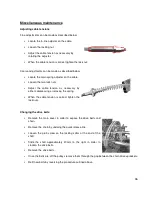
Page 36: ...ust the cable tension as necessary by either compressing or relaxing the spring When the cable tension is correct tighten the lock nuts Changing the drive belts Remove the main cover in order to expose the drive belts and chain Remove the chain by undoing the quick release link Loosen the grub screw on the locking collar at the end of the shaft Slide the shaft approximately 20mm to the right in or...

Page 37: ...e Turfmech Allett parts if new parts are required Check all bolts and tighten as necessary Repair any damaged paint work Apply a wax coat to all panels standard automotive wax can be used Allow all belts to dry before storing Lubricate all grease points and apply a thin coat of chain lubricant to the chains Preparing the engine Drain the fuel For a small amount of fuel start the engine and allow i...

Page 38: ...38 Removing from storage Carry out the daily inspection list Open the fuel shut off tap Check tyre pressures where fitted ...

Page 39: ...onditions Increase height of cut change direction of cut Ribbing of grass perpendicular to direction of travel Cylinder speed too slow for forward travel speed Forward travel speed too fast Increase engine speed Reduce forward travel speed Tram lining of grass in the direction of forward travel Bottom blade in ground contact Poor cylinder to bottom blade adjustment Increase height of cut Re adjust...

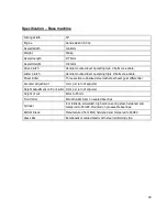
Page 40: ...ller Three section rubberised steel with steel bevel gear differential Groomer Adjustment 1mm per turn of adjuster Height Adjustment on front roller 1mm per turn of adjuster Height of cut 8mm to 55mm Front roller Smooth Aluminium on sealed bearings Cylinder 6 or 8 Blade all welded high carbon spring steel hardened and tempered to 45HRC Mounted on greaseable bearings Bottom Blade Manufactured from ...

Page 41: ...idth Overall Width 34 Scarifier 29kg 863mm 978mm 24 Verticutter 30kg 863mm 978mm 34 Brush 25kg 863mm 978mm Cutting rates 6 Blade 94 Cuts per metre 86 cuts per yard 2 39 cuts per inch 8 Blade 125 Cuts per metre 114 cuts per yard 3 18 cuts per inch ...

Page 42: ...42 ...

Page 43: ...43 C34 PARTS SECTION ...

Page 44: ...44 ...

Page 45: ... REAR ROLLER ASS Y MAINFRAME ASS Y COUNTERSHAFT BRAKE SIDE ASS Y KICKSTAND ASS Y COUNTERSHAFT ENGINE SIDE ASS Y HANDLE BAR ASS Y GRASSBOX ASS Y LOWER HANDLE BAR ASS Y FRONT ROLLER ASS Y HONDA ENGINE GX200 ...

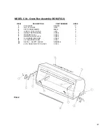
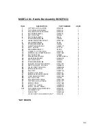
Page 46: ... WASHER M8 WM8 4 4 FRONT ROLLER PLAIN 34 BSG1267 1 5 FRONT ROLLER SHAFT 34 C1582 1 6 BEARING 20mm AM81007 2 7 LOCKING COLLAR BG003 2 8 FRONT ROLLER ADJUSTER AB1072 2 9 SET SCREW M10X25 M1025 2 10 SPRING WASHER M10 SWM10 2 11 GRUB SCREW M8 x 8 ACGM8 2 12 GREASE SEAL TC AM81513 2 4 12 FRONT ROLLER COMPLETE C063 1 MODEL C34 Front Roller Assembly FIG 1 ...

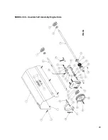
Page 47: ...PR4320 17 2 NUT PLAIN M8 NM8 4 3 SET SCREW M8X25 M825 4 4 G BOX LOCATOR FAB C320 2 5 HEIGHT SETTING BAR C1598 1 6 GRASSBOX C34 C1556 1 7 REINFORCING PLATE C1593 2 8 R H GRASS BOX ARM C1592 1 9 L H GRASSBOX ARM C1591 1 10 DECAL ALLETT LARGE AM81545 1 11 34 B GRASSBOX STIFFENER C1590 1 FIG 2 ...

Page 48: ...SCREW 3 8 UNF x 1 ZC S11014 1 20 SPRING WASHER M10 SWM10 6 21 M10 PLAIN WASHER WM10 11 22 CUTTER CLUTCH CABLE BSG1077 1 23 DRIVE CLUTCH ARM FAB BSG064 1 24 YOKE ANCHOR POINT BSG1024 7 25 BRONZE BUSH AM82654 1 26 CLUTCH ARM SWIVEL BSG017 1 27 BEARING BOSS BSG20 1 28 NEEDLE ROLLER AM81002 2 29 2 GROOVE DRIVE CLUTCH JOCKEY BSG098 1 30 WASHER M6 FORM G Z C WM6G 3 31 SPRING WASHER M6 SWM6 2 32 SET SCRE...

Page 49: ...49 MODEL C34 Countershaft Assembly Engine Side FIG 3A ...

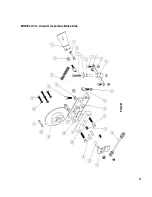
Page 50: ...4 1 11 PLAIN NUT M6 NM6 2 12 CABLE ANCHOR PLATE FAB BSG012 1 13 BRAKE MOUNT BRKT FAB C313 1 14 SET SCREW M8X45 SM845 2 15 BRAKE SPRING C1567 1 16 OPERATING LINK FAB C315 1 17 ACTUATING LEVER C1562 1 18 STUD C1566 2 19 DOWEL PIN AM81505 2 20 ACTUATING BLOCK C1561 1 21 BRAKE PAD C1564 1 22 PRESSURE PLATE C1565 1 23 HUB FOR BRAKE DISC C1558 1 24 BRAKE DISC C1557 1 25 KEY FORM AB AM81463 1 26 SPRING W...

Page 51: ...51 MODEL C34 Counter Assembly Brake Side FIG 3B ...

Page 52: ...R USED 1 PLAIN NUT M8 NM8 2 2 STAY MOUNT BRKT FAB C323 1 3 PLAIN NUT M6 NM6 1 4 SPRING RT 00003098 2 5 SET SCREW M6X25 M625 1 6 SET SCREW M8X25 M825 2 7 SET SCREW M6X35 M635 1 8 SET SCREW M8X45 M845 1 9 PLAIN WASHER M8 WM8 1 10 NUT NYLOC M8 NNM8 1 11 STAY LEG FAB C322 1 ...

Page 53: ...53 MODEL C34 Kickstand Assembly FIG 4 ...

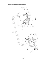
Page 54: ...D BSG1020 2 16 SET SCREW M8 SM845 4 17 WASHER M8 FORM G WM8 FORM G 4 18 UNIVERSAL MOUNT AM81320 4 19 NUT NYLOC M10 NNM10 4 20 SPRING WASHER M8 SWM8 4 21 SPACER FOR A V MOUNTING BSG1207 4 22 SWITCH ON OFF ROCKER AM85043 1 23 ON OFF SWITCH DECAL AM81555 1 24 BRAKE LEVER FAB BSG045 1 25 FLAT CAP AM81140 1 26 SCREW LOCK BODY BSG046 1 27 BRAKE LEVER BASS PLATE BSG1089 1 28 YOKE ANCHOR POINT BSG1024 4 2...

Page 55: ...55 MODEL C34 Handle Bar Assembly FIG 5 ...

Page 56: ...VOT BRAKCET BSG110 1 6 NUT NYLOC M10 NNM10 4 7 PLAIN NUT M10 NM10 2 8 SET SCREW M8X25 M825 2 9 PLAIN NUT M8 NM8 2 10 SET SCREW M6X20 M620 2 11 PLAIN NUT M6 NM6 2 12 SPRING RT 00003098 2 13 WASHER M10 FORM G WM10G 2 14 RH PIVOT BRACKET BSG111 1 15 SPACER HYDRO BOSS AFK1132 2 16 LOWER BUFFER BSG1236 2 17 TOP BUFFER BSG1235 2 18 SPRING ANCHOR FAB BSG109 2 19 BOLT M10X55 BM1055 2 20 PLAIN WASHER M10 W...

Page 57: ...57 MODEL C34 Lower Handle Bar Assembly FIG 6 ...

Page 58: ...E GEAR AB055 1 11 KEY FORM A AM92888 2 12 PARALLEL KEY FORM C AM81125 1 13 REAR ROLLER CENTRE FAB AB053 1 14 DIFF PINION 12 TOOTH HUB AB1053 1 15 WASHER M6 MUDGAURD WM6 MG 1 16 SPRING WASHER M6 SWM6 9 17 SET SCREW M6X12 SM612 1 18 SPACER DIFFERENTIAL AB1051 4 19 CIRCLIP EXTERNAL S019M AM81126 1 20 BEARING 25mm AM85314 2 21 SPRING WASHER WM6 9 22 RING GEAR 28T AB1056 2 23 REAR ROLLER TAB WASHER BSG...

Page 59: ...59 MODEL C34 REAR ROLLER ASSEMBLY FIG 7 ...

Page 60: ...047 1 22 TOP BELT GUIDE FAB C318 2 23 SET SCREW 3 8 1 1 2 UNF S11011 2 24 CHAIN TENSIONER ASM Y BSG034 1 25 SET SCREW 3 8 1 UNF S11014 3 26 SET SCREW M8X16 SM816 1 27 WASHER PLAIN M8 WM8 1 28 SPRING WASHER M8 SWM8 1 29 COMPOUND SPROKET FAB BSG033 1 30 CHAIN FOLDED 3 8 80 LINKS C1601 1 31 TOP SPROCKET BSG022 1 32 NUT PLAIN M8 NM8 1 33 PULLEY TRIPLE AM94027 1 34 POWER UNIT CHASIS FAB C317 1 35 UNION...

Page 61: ...61 MODEL C34 Main Frame Assembly FIG 8 ...

Page 62: ... C1532 2 10 ACCESSORY DEFLECTOR PLATE C1613 1 11 BEARING 20MM FLANGED AM81008 2 12 SET SCREW 6X16 SM616 9 13 WASHER PLAIN M6 WM6 9 14 NUT NYLOC M6 NNM6 9 15 SCREW M6 x 16 ROOFING BOLT ZC S11060 1 16 SCREW 3 8X3 4 UNF S11011 4 17 WASHER SPRING 3 8 SW 3 8 4 18 WASHER SPRING M12 ZC SWM12 4 19 SET SCREW 12X55 M1255 4 20 SET SCREW M12X30 M1230 4 21 WASHER PLAIN M12 WM12 4 22 NUT NYLOC M12 NNM12 4 23 CY...

Page 63: ...63 MODEL C34 BRUSH CARTRIDGE FIG 9 ...

Page 64: ...WASHER PLAIN M6 WM6 9 14 NUT NYLOC M6 NNM6 9 15 SCREW M6 x 16 ROOFING BOLT ZC S11060 1 16 SCREW 3 8X3 4 UNF S11011 4 17 WASHER SPRING 3 8 SW 3 8 4 18 WASHER SPRING M12 ZC SWM12 4 19 SET SCREW 12X55 M1255 4 20 SET SCREW M12X30 M1230 4 21 WASHER PLAIN M12 WM12 4 22 NUT NYLOC M12 NNM12 4 23 CYLINDER BLADE WARNING DECAL AM81541 1 24 CE PLATE T000333 1 25 SCARIFIER VERTI CUTTER SHAFT C1542 1 26 WASHER ...

Page 65: ...65 MODEL C34 VERTICUTTER CARTRIDGE FIG 10 ...

Page 66: ...20MM FLANGED LFTCB11010 AM81008 2 14 C34 TUNGSTEN TIPPED SCARIFIER AM81506 49 15 WASHER PLAIN M24 WM24 1 16 CIRCLIP EXTERNAL DOMED AM81229 1 17 NUT HALF M24 NHM24 1 18 WASHER PLAIN M24 WM24 1 19 M24 TOOTHED SHAKEPROOF WASHER WM24TI 1 20 SET SCREW M6X16 M616 9 21 WASHER PLAIN M6 WM6 9 22 NUT NYLOC M6 NNM6 9 23 SCREW M6 x 16 ROOFING BOLT ZC S11060 1 24 SCREW 3 8X3 4 UNF S11011 4 25 WASHER SPRING 3 8...

Page 67: ...67 MODEL C34 SCARIFIER CARTRIDGE FIG 11 ...

Page 68: ...1 11 BEARING 20MM FLANGED LFTCB11010 AM81008 2 12 SET SCREW M6X16 M616 9 13 WASHER PLAIN M6 WM6 9 14 NUT NYLOC M6 NNM6 9 15 SCREW M6 x 16 ROOFING BOLT ZC S11060 1 16 SCREW 3 8X3 4 UNF S11011 4 17 WASHER SPRING 3 8 SW 3 8 4 18 WASHER SPRING M12 ZC SWM12 4 19 SET SCREW 12X55 M1255 4 20 SCREW 3 8X3 4 UNF S11011 4 21 WASHER PLAIN M12 WM12 4 22 NUT NYLOC M12 NNM12 4 23 CYLINDER BLADE WARNING DECAL AM81...

Page 69: ...69 MODEL C34 SORREL ROLLER CARTRIDGE FIG 12 ...

Page 70: ...ING WASHER M12 SWM12 4 10 CE PLATE T000333 1 11 DRIVE SIDEPLATE FAB CYL C326 1 12 DEFLECTOR STRIP 34 FAB BSG091 1 13 LIFT BAR FAB 34 C324 1 14 DECAL BOTTOM BLADE ADJ AM81540 1 15 TIE BAR 34 C1532 2 16 DELIVERY PLATE 34 PLASTIC AB1043 1 17 NUT NYLOC M6 NNM6 15 18 WASHER PLAIN M6 WM6 15 19 SUPPORT PLATE C1612 1 20 SET SCREW M6X16 M616 1 21 NUT NYLOC M12 NNM12 4 22 NON DRIVE SIDEPLATE FAB CYL C327 1 ...

Page 71: ...71 MODEL C34 CUTTING CYLINDER 6 BL CARTRIDGE FIG 13 ...

Page 72: ...ING WASHER M12 SWM12 4 10 CE PLATE T000333 1 11 DRIVE SIDEPLATE FAB CYL C326 1 12 DEFLECTOR STRIP 34 FAB BSG091 1 13 LIFT BAR FAB 34 C324 1 14 DECAL BOTTOM BLADE ADJ AM81540 1 15 TIE BAR 34 C1532 2 16 DELIVERY PLATE 34 PLASTIC AB1043 1 17 NUT NYLOC M6 NNM6 15 18 WASHER PLAIN M6 WM6 15 19 SUPPORT PLATE C1612 1 20 SET SCREW M6X16 M616 1 21 NUT NYLOC M12 NNM12 4 22 NON DRIVE SIDEPLATE FAB CYL C327 1 ...

Page 73: ...73 MODEL C34 CUTTING CYLINDER 6 BL CARTRIDGE FIG 14 ...

Page 74: ...74 Notes ...

Reviews: