11
Operation
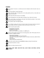
Do not operate the engine in a confined space where dangerous carbon monoxide fumes can
collect.
Mow only in daylight or in good artificial light.
Before starting the engine, disengage drive to the cutting cylinder and the rear drive roller and
engage the parking brake.
Watch out for traffic when crossing or near roadways.
Always disengage drive to the cylinder before travelling over any surface other than grass.
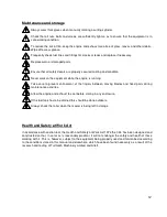
When using the mower, never direct the discharged material towards bystanders or allow anyone
near the machine whilst it is in operation.
Never operate a mower with defective guards.
Do not attempt to increase the factory set maximum speed of the engine. Operating an engine at
excessive speed will lead to increased wear and tear and increases the risk of injury.
Before leaving the operator position:
-
Disengage drive to the rollers.
-
Disengage drive to the cylinder.
-
Engage the parking brake.
-
Switch the on/off switch on the handlebars to the
OFF
position.
Engage the parking brake, disengage drive to the cutting cylinder, switch off the engine and ensure
the cylinder is completely stationary:
-
Before releasing blockages.
-
Before checking, cleaning or working on the machine.
-
After striking a foreign object inspect the mower for damage and rectify any problems before
continuing.
-
Before refuelling.
-
Before making cutter head adjustments.
If the machine starts to vibrate abnormally
STOP
immediately and check the machine over.
Never park the machine on a slope.
Reduce the throttle setting during run out
ALWAYS KEEP HANDS AND FEET WELL AWAY FROM A ROTATING CUTTING
CYLINDER.
Summary of Contents for C 34
Page 2: ...2 ...
Page 27: ...27 ...
Page 42: ...42 ...
Page 43: ...43 C34 PARTS SECTION ...
Page 44: ...44 ...
Page 49: ...49 MODEL C34 Countershaft Assembly Engine Side FIG 3A ...
Page 51: ...51 MODEL C34 Counter Assembly Brake Side FIG 3B ...
Page 53: ...53 MODEL C34 Kickstand Assembly FIG 4 ...
Page 55: ...55 MODEL C34 Handle Bar Assembly FIG 5 ...
Page 57: ...57 MODEL C34 Lower Handle Bar Assembly FIG 6 ...
Page 59: ...59 MODEL C34 REAR ROLLER ASSEMBLY FIG 7 ...
Page 61: ...61 MODEL C34 Main Frame Assembly FIG 8 ...
Page 63: ...63 MODEL C34 BRUSH CARTRIDGE FIG 9 ...
Page 65: ...65 MODEL C34 VERTICUTTER CARTRIDGE FIG 10 ...
Page 67: ...67 MODEL C34 SCARIFIER CARTRIDGE FIG 11 ...
Page 69: ...69 MODEL C34 SORREL ROLLER CARTRIDGE FIG 12 ...
Page 71: ...71 MODEL C34 CUTTING CYLINDER 6 BL CARTRIDGE FIG 13 ...
Page 73: ...73 MODEL C34 CUTTING CYLINDER 6 BL CARTRIDGE FIG 14 ...
Page 74: ...74 Notes ...


