061090 - 12/2013
SECTION 3
SERVICE
Page 3-14
Belt Tensioning
These tolerances are for reference only. For fixed center drive applications
and special tolerances, contact Gates Power Transmission Product
Application.
Standard Belt Tensioning Procedure
When installing a Gates belt:
A. Be sure it is tensioned adequately to prevent tooth jumping
(ratcheting) under the most severe load conditions which the
drive will encounter during operation.
B. Avoid extremely high tension which can reduce belt life and
possibly damage bearings, shafts and other drive components.
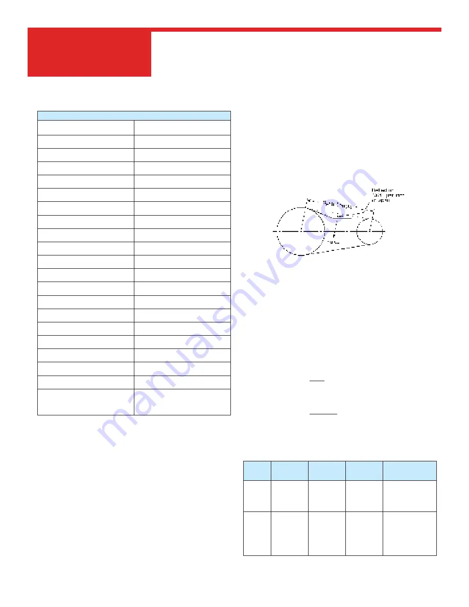
The proper way to check belt tension is to use a tension tester. Gates has
a variety of tension testers, ranging from the simple spring scale type
tester to the sophisticated Sonic Tension Meter. The spring scale type
tester is used by measuring how much force is required to deflect the belt
at the center of its span by a specified distance (force deflection method),
as shown in the sketch below.
The Sonic Tension Meter measures the vibration of the belt span and
instantly converts the vibration frequency into belt static tension (span
vibration method).
When you wish to use a numerical method for calculating recommended
belt installation tension values, the following procedure may be used.
STEP 1: Calculate the required base
static installation tension.
Use Formula 14 to calculate the required base static installation
tension.
Formula 14
T
st
=20HP +mS
2
S
Where:
T
st
= base static installation tension, pounds
HP = Horsepower
S = PD x RPM
3820
m = Value from Table 10
PD = Sprocket Pitch Diameter, inches
RPM = Revolutions per minute of same sprocket
Table 10
Pitch
Belt Width
m
Y
Minimum T
st
(lb)
per span
8mm
12mm
21mm
36mm
62mm
0.33
0.57
0.97
1.68
43.83
76.70
131.49
226.45
28
49
84
145
14mm
20mm
37mm
68mm
90mm
125mm
0.92
1.69
3.11
4.12
5.72
134.57
248.95
457.52
605.55
841.04
119
220
405
536
744
Stock Belt Center Distance Tolerances
Belt Length
(mm)
(in)
Center Distance
(mm)
Tolerance
(in)
over
127
to
254
5
10
± 0.20
.008
over
254
to
381
10
15
± 0.23
.009
over
381
to
508
15
20
± 0.25
.010
over
508
to
762
20
30
± 0.30
.
012
over
762
to 1016
30
40
± 0.33
.
013
over
1016
to 1270
40
50
± 0.38
.
015
over
1270
to 1524
50
60
± 0.41
.
016
over
1524
to 1778
60
70
± 0.43
.
017
over
1778
to 2032
70
80
± 0.46
.
018
over
2032
to 2286
80
90
± 0.49
.
019
over
2286
to 2540
90
100
± 0.52
.
020
over
2540
to 2794
100
110
± 0.54
.
021
over
2794
to 3048
110
120
± 0.56
.
022
over
3048
to 3302
120
130
± 0.58
.
023
over
3302
to 3556
130
140
± 0.60
.
024
over
3556
to 3810
140
150
± 0.63
.
025
over
3810
to 4064
150
160
± 0.66
.
026
over
4064
to 4318
160
170
± 0.69
.
027
over
4318
to 4572
170
180
± 0.72
.
028
over
4572
180
add ±
.03
for
.001
every
.254 increment
10
Summary of Contents for 060800
Page 1: ...OPERATIONS PARTS MANUAL 061090 12 2013 Riding Trowel ALSO INCLUDES 450C 05 2016 ...
Page 14: ...061090 12 2013 Page xii Dimensional Specifications ...
Page 16: ...061090 12 2013 INTENTIONALLY BLANK Page xiv ...
Page 17: ...061090 12 2013 SECTION 1 SAFETY Page 1 1 Section 1 SAFETY ...
Page 18: ...061090 12 2013 SECTION 1 SAFETY Page 1 2 State Regulations Proposition 65 Warning ...
Page 19: ...061090 12 2013 SECTION 1 SAFETY Page 1 3 Federal Regulations Respiratory Hazards ...
Page 33: ...061090 12 2013 SECTION 2 OPERATIONS Page 2 1 Section 2 OPERATIONS ...
Page 41: ...061090 12 2013 SECTION 3 SERVICE Page 3 1 Section 3 SERVICE ...
Page 57: ...061090 12 2013 SECTION 4 PARTS Page 4 1 Section 4 PARTS ...
Page 104: ...061090 12 2013 SECTION 4 PARTS Page 4 48 Electrical Schematic Illustration ...
Page 105: ...061090 12 2013 SECTION 4 PARTS Page 4 49 Electrical Schematic Illustration ...


