


Speed Regulation
101
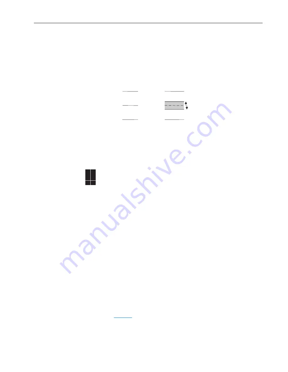
Min/Max Speed
Maximum and minimum speed limits are applied to the reference. These limits
apply to the positive and negative references. The minimum speed limits will create
a band that the drive will not run continuously within, but will ramp through. This is
due to the positive and negative minimum speeds. If the reference is positive and
less than the positive minimum, it is set to the positive minimum. If the reference is
negative and greater than negative minimum, it is set to the negative minimum. If
the minimum is not 0, hysteresis is applied at 0 to prevent bouncing between
positive and negative minimums. See below.
Maximum frequency
The maximum frequency defines the maximum reference frequency. The actual
output frequency may be greater as a result of slip compensation and other types of
regulation.
Speed Regulation
The drive achieves speed regulation by adjusting the output frequency to
compensate for load changes.
The [Feedback Select] parameter selects the speed regulation method as follows:
•
Open Loop
•
Slip Compensation
•
Encoder
•
Simulator
Open Loop
As the load on an induction motor increases, the rotor shaft speed decreases,
creating slip (and therefore torque) to drive the load. In open loop mode, motor
speed will be dependent on load changes and the drive will make no attempt to
compensate. The amount of speed change (slip) from no load to full load is a
function of motor design, but is typically 3% of base synchronous speed (e.g. 3% of
1800 RPM = 54 RPM). This “slip” is constant across the speed range.
Slip Compensation
When slip compensation mode is selected, the drive automatically adds the
appropriate amount of output frequency to maintain a consistent motor speed
independent of load. During drive commissioning [Slip RPM @ FLA] is set based
on entered motor nameplate information. This parameter may be adjusted to
provide more or less slip.
See
Figure 18
for a comparison of operation with and without slip compensation.
This shows that over time, slip compensation will correct for changes in load
(curved lines). In contrast, open loop operation shows that no correction is made
based on load.
Band
Max Spd
Min Spd
– Max Spd
Max Spd
Min Spd
– Min Spd
– Max Spd
70EC
700VC
700H
✔ ✔