108
Rockwell Automation Publication 2097-UM002D-EN-P - April 2017
Chapter 6
Kinetix 350 Drive Safe Torque-off Feature
Kinetix 350 Drive Safe
Torque-off Wiring Diagrams
This section provides typical wiring diagrams for the Kinetix 350 drive safe
torque-off feature with other Allen-Bradley safety products.
For additional information regarding Allen-Bradley safety products, including
safety relays, light curtain, and gate interlock applications, refer to the Safety
Products Catalog, website
http://www.rockwellautomation.com/global/
.
The drive is shown in a single-axis relay configuration for category 0 stop per
EN-60204-1 Safety of Machinery Directive.
examples, however, and user applications can differ based on the required
overall machine-performance level requirements.
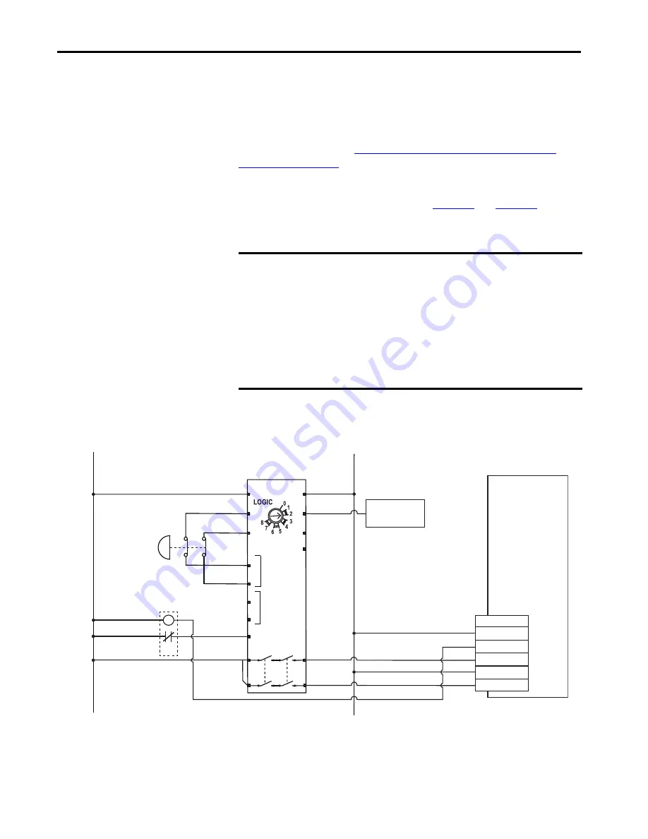
Figure 50 - Single-axis Relay Configuration (Stop Category 0) with Automatic Reset
IMPORTANT
The Kinetix 350 drive meets the requirements of EN ISO 13849-1 Safety of
Machinery, Safety-related Parts of Control Systems, category (CAT 3),
performance level (PL)d and Safety Integrity Level (SIL) 2 per EN 61800-5-
2:2007. Dual inputs and drive monitoring of the safe torque-off circuit, STO-
4 and ST0-6, are done to prevent drive enable if either or both of these
inputs do not function.
It is suggested to evaluate the entire machine performance level that is
required with a risk assessment and circuit analysis. Contact your local
distributor or Rockwell Automation Sales for more information.
+24V DC
COM
Status
Safety Input 1
Safety Common
Safety Input 2
1
2
3
4
5
6
440R-D22R2
Input 1
DI
Input 2
A1
S11
S21
S12
S22
S32
S42
S34
13
23
A2
Y32
L12
L11
14
24
CR1
+
-
Kinetix 350 Drive
Safe Torque-off (STO)
Connector with
Wiring Header
External 24V COM
Safe Torque-off
Demand
Ex24V
Allen-Bradley®
Monitoring Safety Relay
MSR127RP (440R-N23135)
Auxiliary Signal
to PLC
Pins 1 and 2 are not used when using Safety Inputs.
Pin 3 is a sinking output.


