


4–2
Writing Configuration to and Reading Status from Your Module with a Remote I/O Adapter
Publication 1794-6.5.16 – September 1998
During normal operation, the processor transfers from 1 to 4 words
to the module when you program a BTW instruction to the module’s
address.
Read programming moves status and data from the Pulse Counter
module to the processor’s data table in one I/O scan. The processor’s
user program initiates the request to transfer data from the Pulse
Counter module to the processor.
The following read and write words and bit/word descriptions
describe the information written to and read from the Pulse Counter
module. The module uses up to 11 words of input data and up to 3
words of output data. Each word is composed of 16 bits.
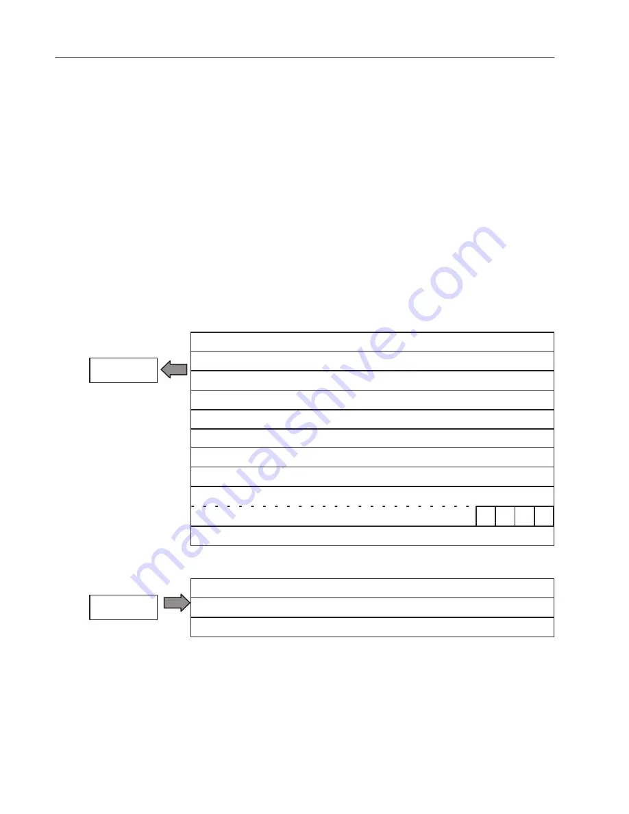
Pulse Counter Module (1794-IP4) Image Table Mapping
Module Image
I/O Image
Input Size
Output Size
0 to 3 Words
1 to 10 Words
Counter 00 – 16–bit period measurement or low word of 32-bit period measurement for channel 0
Code for identification of software version
Control Word 0 – Sets the measure function
Control Word 2 – sets the start of a new measurement
Control Word 1 – Sets the clock frequency and period multiple
Counter 01 – pulse counter for channel 0 or high word of 32-bit period measurement
Counter 10 – 16–bit period measurement or low word of 32-bit period measurement for channel 1
Counter 11 – pulse counter for channel 1 or high word of 32-bit period measurement
Counter 20 – 16–bit period measurement or low word of 32-bit period measurement for channel 2
Counter 21 – pulse counter for channel 2 or high word of 32-bit period measurement
Counter 30 – 16–bit period measurement or low word of 32-bit period measurement for channel 3
Counter 31 – pulse counter for channel 3 or high word of 32-bit period measurement
Readback of Control word 2 or
Reserved
M0
M1
M2
M3
Reading Data From Your
Module
Mapping Data for the
Module